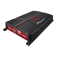
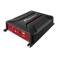
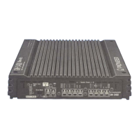
The provided document is a service manual for the Pioneer GM-A6704 series of bridgeable four-channel power amplifiers, including models GM-A6704/XEUC, GM-A6704/XEEW5, GM-A6704/XEVES, and GM-A6704/XEVID.
Function Description
The Pioneer GM-A6704 is a bridgeable four-channel power amplifier designed to enhance car audio systems. It features multiple input options, including RCA and speaker-level inputs, and provides amplified output to speakers. The amplifier incorporates various controls for sound customization, such as HPF (High Pass Filter) frequency, LPF/HPF (Low Pass Filter/High Pass Filter) selection, gain adjustment, and bass boost. It also includes a protection circuit to safeguard against overheating, overvoltage, and speaker output issues.
The amplifier's block diagram illustrates its internal architecture, which includes:
- Input Stage: RCA and speaker-level inputs are fed into isolator circuits (IC2-A/B, IC7-A/B) and low input OP amps (IC1-A/B, IC6-A/B) for signal conditioning.
- Filtering and Control: Dedicated ICs (IC4-A/B, IC10-A/B) handle low-pass and high-pass filtering. Input switching (SW3) allows selection between 2-channel and 4-channel input modes. Bass boost (IC5-A/B) and level control (SW4) provide further sound customization.
- Amplification Stage: The processed audio signals are fed into pre-amplifiers and then to power amplifiers (Q139, Q141, Q239, Q241, Q339, Q341, Q439, Q441) responsible for driving the speakers.
- Power Supply: A boost voltage transformer (T1) and rectifier circuits provide the necessary +15V and -15V DC power to the amplifier's internal components.
- Protection Circuit: An integrated protection circuit (IC12) monitors various parameters, including temperature (Q25), high/low voltage, and speaker output (Q1), to prevent damage to the amplifier and connected speakers. Auto-level switching (Q70, Q71, Q72) and mute switching (Q20, Q21, Q22, Q26) are also part of the control system.
Important Technical Specifications
While the manual refers to the Owner's Manual for most specifications, it explicitly states one key technical detail:
- Backup current: 1.0 mA or less.
The parts list provides insights into the components used, including various ICs (J121456500060S, J080004940010S), transistors (e.g., J5201504Y0210S, J502446700010S), diodes (K005041480030S, K041220001000S), fuses (G655253320110S), and resistors/capacitors with specific part numbers. The presence of a 30A fuse (Mark No. 16) indicates the power handling capability of the unit.
Usage Features
The amplifier offers several user-adjustable features accessible from the front and rear panels:
- Front Panel Controls:
- HPF FREQ: Adjusts the high-pass filter frequency (60Hz, 80Hz, 125Hz, 250Hz).
- LPF/HPF: Selects between LPF OFF, HPF, and LPF modes.
- GAIN: Adjusts the input sensitivity (0.3V to 6.5V).
- INPUT SELECT: Switches between 2CH and 4CH input modes.
- BASS BOOST: Adjusts the bass boost level (0dB, 6dB, 12dB).
- Rear Panel Connections:
- POWER: Terminals for power, ground, and system control.
- RCA INPUT: RCA jacks for audio input (CHA, CHB).
- SPEAKER INPUT: Terminals for speaker-level inputs (LCHAR, LCHBR).
- SPEAKER OUTPUT: Terminals for connecting speakers (CHA, CHB, BRIDGED).
- FUSE: Two 25A fuses for power protection.
The "BRIDGEABLE" designation indicates that the amplifier can combine two channels into one higher-power channel, allowing for flexible system configurations, such as driving a subwoofer.
Maintenance Features
The manual provides detailed instructions and precautions for servicing the amplifier:
- Safety Precautions: Emphasizes conforming to regulations, keeping safety during servicing, and being aware of hot heat sink areas.
- Notes on Disassembly/Assembly:
- Always turn off power before disassembling to prevent IC damage.
- Ensure proper reassembly to original status.
- When tightening screws for transistors or diodes, hold the part firmly to prevent turning and potential solder cracks.
- Crucially, install an insulator between the power transistor and heat sink; failure to do so can damage the power transistor.
- Notes on Replacing Parts:
- Handle ICs carefully due to their fragility and susceptibility to electrostatic induction. Use grounded soldering irons and static-charge protected tweezers.
- When replacing parts fixed to the heatsink (e.g., Q141, Q142, D6, D7), a specific procedure is outlined: place the PCB on blocks, outline the original part's position, place the new part within the outline, align it with the PC board, solder, and apply grease (GEM1057) to the back of the part.
- Notes on Soldering: Lead-free solder is used on the PCBs for environmental protection. Technicians must use lead-free solder and appropriate soldering irons for repairs.
- Operation of Protection Circuit: The amplifier incorporates a protection circuit that reduces output power at approximately 80°C heat sink temperature and stops operation at approximately 100°C to prevent damage.
- Check Points After Servicing: A checklist is provided to ensure product quality after servicing, including confirming resolution of customer complaints, normal audio output and operations, and no new cosmetic damage.
- Troubleshooting Flowchart: A comprehensive flowchart guides technicians through diagnosing common issues like "no sound from speaker," "LED glowing blue," "reference voltage incorrect," and "no signal on isolator output or AMP input." It identifies potential causes, such as defective components (e.g., Q141/142, TH1/2, DZ2), short-circuited speaker outputs, or issues with the power supply or signal path.
- Jigs List: Specifies grease (GEM1057) and bond (GYL1006) for assembly, indicating their application to the P.C.B TOTAL ASSY.
- Exploded Views and Parts List: Detailed diagrams and lists of all components, including part numbers, are provided for easy identification and ordering of replacement parts. Parts marked with "*" are generally unavailable, and those with "△" indicate safety-critical components that must be replaced with identical designations.

 Need help?


 To Next Page

 General