Do you have a question about the Pioneer GM-D8704XEVUC and is the answer not in the manual?
General safety guidelines for servicing the product.
Guidelines for safely taking apart and reassembling the unit.
Precautions for handling and replacing components, especially ICs.
Miscellaneous notes, including soldering requirements.
Product specifications, referring to the Owner's Manual for details.
Procedures to verify product quality and customer satisfaction post-service.
List of lubricants and glues used for service procedures.
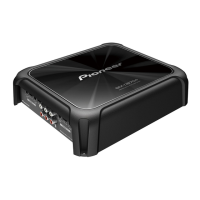
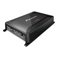
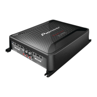
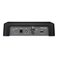
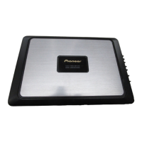
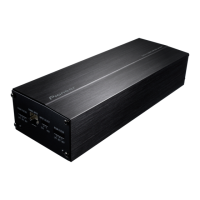
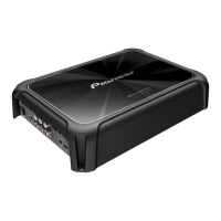
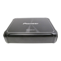
Description of connector functions on the front and rear of the amplifier.
Procedure to remove the chassis from the unit.
Procedure to remove the main Printed Circuit Board assembly.
Exploded view and parts list for the packing components.
Exploded view and parts list for the exterior components.
Schematic diagram of the main Printed Circuit Board.
PCB connection diagram for the main Printed Circuit Board.
| Channels | 4 |
|---|---|
| Max Power Output | 1200 Watts |
| RMS Power Output (4 Ohms) | 100 Watts x 4 |
| RMS Power Output (2 Ohms) | 150 Watts x 4 |
| Bridged RMS Power Output (4 Ohms) | 300 Watts x 2 |
| Frequency Response | 10 Hz to 50 kHz |
| Signal-to-Noise Ratio | 95 dB |
| THD at RMS Output | < 0.05% |
| Crossover Frequency | 40 Hz to 500 Hz |
| Bass Boost | 0-12 dB |
| Low-Pass Filter | 40 Hz to 500 Hz |
| High-Pass Filter | 40 Hz to 500 Hz |