Do you have a question about the Pioneer GM-D8500M/XSUC and is the answer not in the manual?
| Type | Mono |
|---|---|
| Amplifier Class | Class D |
| Number of Channels | 1 |
| RMS Power at 4 Ohms | 300 W |
| RMS Power at 2 Ohms | 500 W |
| Impedance | 1 - 8 Ohms |
| Frequency Response | 10 Hz - 240 Hz |
| Signal-to-Noise Ratio | 100 dB |
| RCA Inputs | Yes |
| Speaker Level Inputs | Yes |
| RMS Power at 1 Ohm | 800W |
| Power Output (RMS) | 800W x 1 (1 Ohm) |
| Power Output (Peak) | 1600 W |
| Peak Power Output (1 Ohm) | 1600W |
| Total Harmonic Distortion (THD) | < 0.05% |
| Low Pass Filter (LPF) | 40 Hz - 240 Hz |
| Bass Boost | 0 - 18 dB |
| Input Sensitivity | 0.2V - 6.5V |
Precautions and warnings for qualified service technicians.
Chemical warning regarding potential health risks.
Ensuring product safety during servicing and repair.
Procedures for optimizing product performance and characteristics.
Guidelines for using specified lubricants, glues, and parts.
Proper methods for cleaning components to restore performance.
Procedures for setting shipping mode or installing screws for transit.
General safety and handling precautions for servicing.
Guidelines and recommendations for lead-free soldering.
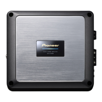
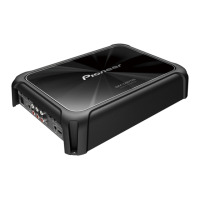
Detailed technical specifications for the GM-D8500M/XSUC amplifier.
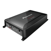
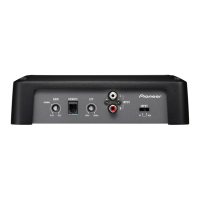
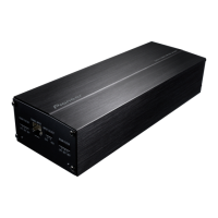
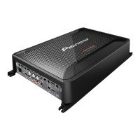
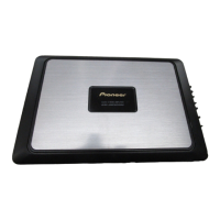
Description and illustration of front and rear panel controls and connectors.
Wiring diagram illustrating all necessary connections for the unit.
Essential checks to perform after completing service or repair.
List of lubricants and glues required for service procedures.
Step-by-step instructions for removing the main case of the unit.
Step-by-step instructions for removing the amplifier unit.
Exploded view and parts list for the packing contents.
Detailed list of parts included in the packing section.
Comparison table highlighting differences between model variants.
Detailed list of parts for the exterior of the unit.
Comparison table highlighting differences between model variants.
Overview schematic diagram of the amplifier unit.
Detailed schematic diagram of the amplifier printed circuit board.
Detailed schematic diagram of the remote control printed circuit board.
Component layout and connection points for the amplifier PCB.
Component layout diagram for AMP PCB SIDE A.
Component layout diagram for AMP PCB SIDE B.
Component layout diagram for AMP PCB SIDE B.
Component layout diagram for REMOTE PCB SIDE A.
Component layout diagram for REMOTE PCB SIDE B.
List of miscellaneous electrical components and their part numbers.
List of resistors with circuit symbols and associated part numbers.
List of capacitors with circuit symbols and associated part numbers.
Continuation of the capacitor list with circuit symbols and part numbers.