Do you have a question about the Pioneer GM-D9701/XEVEW5 and is the answer not in the manual?
| Amplifier Class | Class D |
|---|---|
| Number of Channels | 1 |
| Peak Power Output | 2400 W |
| Frequency Response | 10 Hz to 240 Hz |
| Signal to Noise Ratio | 100 dB |
| Crossover Frequency | 40 Hz to 240 Hz |
| Bass Boost | 0 to 18 dB |
| Bass Boost Frequency | 50 Hz |
| Fuse Rating | 40 A x 3 |
| RMS Power at 4 Ohms | 500 W |
| RMS Power at 2 Ohms | 800 W |
| RMS Power at 1 Ohm | 1200 W |
| Low Pass Filter | 40 Hz to 240 Hz |
| Input Sensitivity | 0.2V - 6.5V |
| Operating Voltage | 14.4 V (11 V to 16 V allowable) |
| Weight | 3.4 kg |
| Input Level Control | 0.2V - 6.5V |
General safety, disassembly, and parts replacement notes for qualified service technicians.
Guidelines for safely taking apart and reassembling the unit, emphasizing power-off procedures.
Precautions for handling and replacing components, especially concerning static charge protection.
Notes on using lead-free solder and appropriate soldering irons for environmental protection.
Procedures to confirm product quality, customer complaint resolution, and appearance after servicing.
List of lubricants and glues used in service, specifying their application.
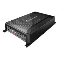
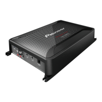
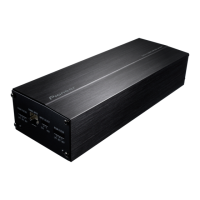
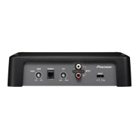
Explanation of the function of various connectors on the front and rear of the unit.
Step-by-step instructions for removing the chassis, starting with six screws.
Exploded view and parts list for the product's packing and accessories.
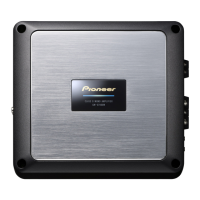
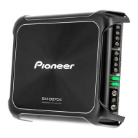
Exploded view and parts list for the product's exterior components.
Comprehensive list of electrical components, including part numbers and circuit symbols.
Detailed schematic diagram of the unit's circuitry, including component designations.
Diagrams showing Printed Circuit Board (PCB) connections and component layouts.