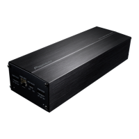
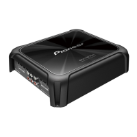
Do you have a question about the Pioneer GM-D9705/XEVEL and is the answer not in the manual?
Conform to regulations and follow safety instructions during servicing.
Turn off power before disassembly, and restore to original status after assembly.
Use static protection, grounded soldering iron, and appropriate tweezers for part replacement.
Use lead-free solder and appropriate soldering iron for environmental protection.
Refer to Owner's Manual for most items; Backup current is 1 mA or less.
Confirm customer complaint solved, check output sound, and appearance.
Lists lubricants and glues used for service, e.g., Grease GEM1057, Bond GYL1006.
There is not information to be shown in this chapter.
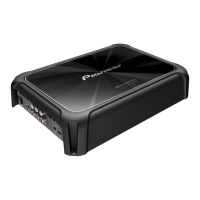
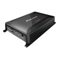
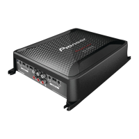
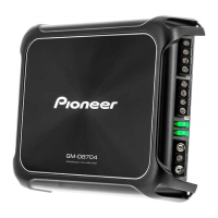
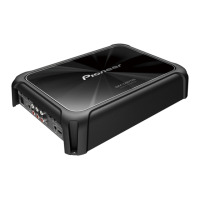
Description of front and rear connector functions and pinouts.
There is not information to be shown in this chapter.
Procedure to remove the chassis by unscrewing 6 pcs.
Procedure to remove the SW-IN PCB by unscrewing 4 pcs.
Remove brackets, thermistor, supporters, and then the MAIN PCB.
There is not information to be shown in this chapter.
Exploded view of the packing section components.
List of parts for the packing section, including owner's manuals and warranty card.
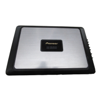
Comparison table for GM-D9705/XEVEL and GM-DX975/XEVEL differences.
Exploded view of the exterior components of the unit.
List of exterior parts, including chassis, screws, brackets, and heat sinks.
Comparison table for GM-D9705/XEVEL and GM-DX975/XEVEL differences.
Schematic diagram for the main PCB assembly.
Schematic diagram for the SW-IN PCB assembly, showing components and connections.
Connection diagram for the main PCB, showing component placement on Side A.
Connection diagram for the main PCB, showing component placement on Side B.
Connection diagram for the SW-IN PCB, showing components on Side A.
Connection diagram for the SW-IN PCB, showing components on Side B.
Electrical parts list including ICs, switches, resistors, and other miscellaneous components.
List of semiconductors like transistors (Q) and diodes (D) with their part numbers.
Continuation of semiconductor parts list including transistors (Q) and diodes (D).
List of coils (L), connectors (CN), and other miscellaneous parts.
List of switches, potentiometers, Zener diodes, and connectors.
Comprehensive list of capacitors with their part numbers and types.
Continuation of capacitor list with additional types and part numbers.
List of miscellaneous parts including rotary potentiometers and modular jacks.
| Channels | 5 |
|---|---|
| Frequency Response | 10 Hz - 50 kHz |
| Bass Boost | 0 - 18 dB |
| Input Sensitivity | 200 mV - 6 V |
| Amplifier Class | Class D |
| Signal to Noise Ratio | 100dB |
| Crossover Frequency | 50Hz - 500Hz |
| Low-Pass Filter | 40 Hz to 240 Hz |