Do you have a question about the Pioneer HTP-105 and is the answer not in the manual?
Check leakage current to earth ground. Must not exceed 0.5mA to ensure safety.
Use specified PIONEER parts for safety. Substitute parts may cause hazards.
Instructions for removing the power amplifier section, including screws and leads.
Method for detaching the grille using a flat blade screwdriver.
Instructions for removing the speaker, involving four screws.
Details about packing materials and their part numbers.
Lists exterior parts with their mark numbers, descriptions, and part numbers.
Lists power amp section components with mark numbers, descriptions, and part numbers.
Guidelines for ordering service parts and understanding schematic symbols.
Explains matching part numbers between PCB and schematic diagrams.
Presents the detailed circuit diagram of the subwoofer.
Lists semiconductor components with part numbers.
Lists resistor types, values, and part numbers.
Lists capacitor types, values, and part numbers.
Lists miscellaneous parts like fuses, screws, and connectors.
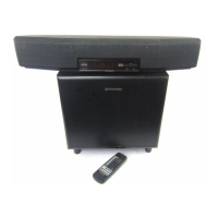
Identifies and explains front panel controls and indicators.
Details the technical specifications of the HTP105/205-SW model.
This document is a service manual for the Pioneer HTP105/205-SW powered subwoofer, providing detailed information for qualified service technicians. It covers safety information, disassembly procedures, exploded views with parts lists, schematic and PCB connection diagrams, PCB parts lists, panel facilities, and technical specifications.
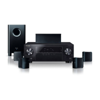
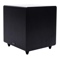
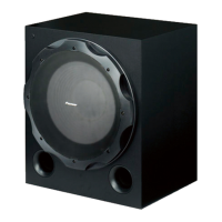
The Pioneer HTP105/205-SW is a powered subwoofer designed to enhance the low-frequency audio output of a home entertainment system. It features a built-in amplifier and is a floor-standing, bass-reflex type unit with a PVC-sheet finish that mimics a wood pattern. The subwoofer is intended to be connected to the SUBWOOFER OUTPUT terminal of a receiver using an RCA cord, providing adjustable bass levels to complement the main audio system.
The subwoofer's rear panel provides key controls and connections for operation:
The manual is primarily a service guide, offering detailed instructions for maintenance and repair:
This manual serves as an essential resource for ensuring the safe and effective repair and maintenance of the Pioneer HTP105/205-SW subwoofer.