EasyManua.ls Logo

Pioneer HTV-SW1 User Manual

Pioneer HTV-SW1
52 pages
To Next Page IconTo Next Page
Page #1 background imageLoading...
Page #1 background image
ORDER NO.
PIONEER ELECTRONIC CORPORATION 4-1, Meguro 1-Chome, Meguro-ku, Tokyo 153-8654, Japan
PIONEER ELECTRONICS SERVICE, INC. P.O. Box 1760, Long Beach, CA 90801-1760, U.S.A.
PIONEER ELECTRONIC (EUROPE) N.V. Haven 1087, Keetberglaan 1, 9120 Melsele, Belgium
PIONEER ELECTRONICS ASIACENTRE PTE. LTD. 253 Alexandra Road, #04-01, Singapore 159936
PIONEER ELECTRONIC CORPORATION 1998
HTV-C1
DDXJ AC110–127V/220–230V/240V With the voltage selector
ADXJ AC power supplied from power trans-
former's secondary of other system component
This product is a system component. This product does not function properly when independent;
to avoid malfunctions, be sure to connect it to the prescribed system component, otherwise
damage may result. The Powered Subwoofer HTV-SW1 is a part of the Hometheater System HTV-
1.
POWERED SUBWOOFER
RRV2060
T–ZZR NOV. 1998 Printed in Japan
HTV-SW1
1. SAFETY INFORMATION.................................... 2
2. EXPLODED VIEWS AND PARTS LIST ............. 3
3. SCHEMATIC DIAGRAM................................... 10
4. PCB CONNECTION DIAGRAM ....................... 24
5. PCB PARTS LIST ............................................. 36
6. ADJUSTMENT.................................................. 39
7.GENERAL INFORMATION ............................... 40
7.1 PARTS ........................................................ 40
CONTENTS
7.1.1 IC ........................................................... 40
7.1.2 DISPLAY................................................ 42
7.2 DIAGNOSIS ................................................ 43
7.3 TEST MODE(HTV-C1) ............................... 45
7.4 INDEPENDENT OPERATION DIAGNOSIS46
7.5 BACKUP FUNCTION (HTV-C1)................. 47
7.6 BLOCK DIAGRAM...................................... 48
8.PANEL FACILITIES AND SPECIFICATIONS ..... 50
THIS MANUAL IS APPLICABLE TO THE FOLLOWING MODEL
(
S
)
AND TYPE
(
S
)
.
CONTROL CENTER
• HTV-SW1
• HTV-C1
SURROUND MODE
STANDBY/ON
DISPLAY INPUT
VOLUME
Hometheater System Control Center
HTV-1 HTV-C1 (this service manual)
(service manual RRV2063)
Powered Subwoofer
HTV-SW1 (this service manual)
The voltage can be converted by
the following method.
Model
HTV-SW1 HTV-C1
Type Power Requirement
Power Amp
HTV-A1 (this service manual)
w
w
w
.
x
i
a
o
y
u
1
6
3
.
c
o
m
Q
Q
3
7
6
3
1
5
1
5
0
9
9
2
8
9
4
2
9
8
T
E
L
1
3
9
4
2
2
9
6
5
1
3
9
9
2
8
9
4
2
9
8
0
5
1
5
1
3
6
7
3
Q
Q
TEL 13942296513 QQ 376315150 892498299
http://www.xiaoyu163.com
Question and Answer IconNeed help?

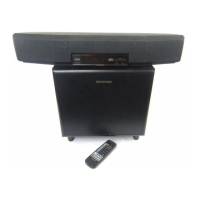
Do you have a question about the Pioneer HTV-SW1 and is the answer not in the manual?

Pioneer HTV-SW1 Specifications

General IconGeneral
TypePowered subwoofer
ConnectivityLine input
Enclosure TypeBass reflex
Crossover Frequency50Hz - 200Hz
Phase Switch0 / 180 degrees

Summary

SAFETY INFORMATION

WARNING

Product contains lead and chemicals known to cause health issues.

LEAKAGE CURRENT CHECK

Procedure for measuring leakage current.

PRODUCT SAFETY NOTICE

Importance of using specified replacement parts for safety.

EXPLODED VIEWS AND PARTS LIST

PACKING PARTS LIST (HTV-SW1)

Exploded view and parts list for packing components of HTV-SW1.

HTV-A1 EXTERIOR AND PARTS

Exploded view and parts list for the exterior and power amp of HTV-A1.

HTV-C1 MAIN SECTION PARTS LIST

List of parts for the main section of HTV-C1.

SCHEMATIC DIAGRAMS

HTV-A1 SCHEMATIC

Schematic diagram for the HTV-A1 amplifier section.

HTV-C1 OVERALL CONNECTIONS

Overall connection schematic for HTV-C1.

DISPLAY ASSY SCHEMATIC

Schematic diagram for the DISPLAY assembly.

PCB CONNECTION DIAGRAMS

HTV-A1 PCB CONNECTIONS

PCB connection diagrams for HTV-A1 sections.

JACK ASSY PCB CONNECTION

PCB connection diagrams for the JACK assembly.

HTV-C1 MAIN ASSY PCB LAYOUT

PCB layout for the HTV-C1 MAIN assembly.

PCB PARTS LISTS

HTV-A1 PCB PARTS LIST

Parts list for HTV-A1 PCB assemblies and components.

HTV-C1 PCB PARTS LIST

Parts list for HTV-C1 PCB assemblies and components.

GENERAL INFORMATION

IC PIN FUNCTIONS

IC pin functions and descriptions for various ICs.

DISPLAY ASSIGNMENTS

Display assembly pin assignment and grid layout.

DIAGNOSIS PROCEDURES

HTV-A1 DISASSEMBLY FOR DIAGNOSIS

Steps for disassembling the HTV-A1 for diagnosis.

HTV-A1 INDEPENDENT OPERATION DIAGNOSIS

Method for independent operation diagnosis of HTV-A1.

TEST MODE (HTV-C1)

ENTRY INTO TEST MODE

Methods to enter test mode for HTV-C1.

DSP CHECK PROCEDURE

Procedure for DSP check mode testing.

TEST MODE OPERATION

Operations within test mode, including FL segment check.

PANEL FACILITIES AND SPECIFICATIONS

CONTROL CENTER (HTV-C1) PANEL OVERVIEW

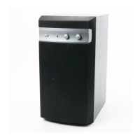
Overview of the control center's panel layout and functions.
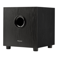
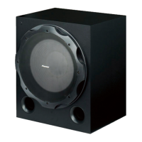
REMOTE CONTROL UNIT

Related product manuals