EasyManua.ls Logo

Pioneer S-RS3SW Service Manual

Pioneer S-RS3SW
36 pages
To Next Page IconTo Next Page
Page #1 background imageLoading...
Page #1 background image
ORDER NO.
PIONEER CORPORATION 4-1, Meguro 1-chome, Meguro-ku, Tokyo 153-8654, Japan
PIONEER ELECTRONICS (USA) INC. P.O. Box 1760, Long Beach, CA 90801-1760, U.S.A.
PIONEER EUROPE NV Haven 1087, Keetberglaan 1, 9120 Melsele, Belgium
PIONEER ELECTRONICS ASIACENTRE PTE. LTD. 253 Alexandra Road, #04-01, Singapore 159936
PIONEER CORPORATION
2008
2008 Printed in Japan
POWER ON
S-RS3SW
RRV3797
POWERED SUBWOOFER
S-RS3SW
THIS MANUAL IS APPLICABLE TO THE FOLLOWING MODEL(S) AND TYPE(S).
Model Type Power Requirement Remarks
S-RS3SW WDLPWXJ AC 220 V to 240 V
S-RS3SW LFXJ AC 110 V to 127 V
For details, refer to "Important Check Points for good servicing".
T-ZZR AUG.
w
w
w
.
x
i
a
o
y
u
1
6
3
.
c
o
m
Q
Q
3
7
6
3
1
5
1
5
0
9
9
2
8
9
4
2
9
8
T
E
L
1
3
9
4
2
2
9
6
5
1
3
9
9
2
8
9
4
2
9
8
0
5
1
5
1
3
6
7
3
Q
Q
TEL 13942296513 QQ 376315150 892498299
http://www.xiaoyu163.com

Other manuals for Pioneer S-RS3SW

Question and Answer IconNeed help?

Do you have a question about the Pioneer S-RS3SW and is the answer not in the manual?

Pioneer S-RS3SW Specifications

General IconGeneral
BrandPioneer
ModelS-RS3SW
CategorySubwoofer
LanguageEnglish

Summary

Important Check Points for Good Servicing

1. Product safety

Guidelines for safe repair practices, including equipment use and environment.

SERVICE PRECAUTIONS

1.1 NOTES ON SOLDERING

Precautions and guidance for using lead-free solder during repair work.

SPECIFICATIONS

2.1 SPECIFICATIONS

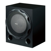
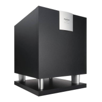
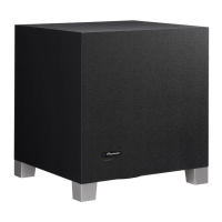
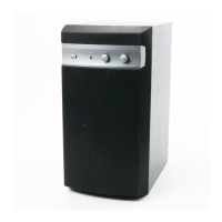
Technical details of the S-RS3SW subwoofer, including power, dimensions, and requirements.

DISASSEMBLY

7.1 DISASSEMBLY

Step-by-step procedures for disassembling the amplifier section of the unit.

EXPLODED VIEWS AND PARTS LIST

EXTERIOR SECTION

AMP SECTION

(1) AMP SECTION PARTS LIST

Detailed list of parts for the amplifier section with part numbers.

SCHEMATIC DIAGRAM

10.1 POWER AMP ASSY

Schematic for the power amplifier assembly, detailing components and connections.

10.2 TRANS ASSY

Schematic for the transformer assembly, showing its connections and components.

10.5 REGULATOR ASSY

Schematic for the regulator assembly, detailing its connections and components.

PCB CONNECTION DIAGRAM

11.2 AMP ASSY

PCB diagram for the amplifier assembly, detailing component placement and layout.

11.3 JACK, REGULATOR AND TRANS ASSYS

PCB diagrams for Jack, Regulator, and Transformer assemblies.

PCB PARTS LIST

Related product manuals