EasyManua.ls Logo

Pioneer Lexus SC400 User Manual

Pioneer Lexus SC400
58 pages
To Next Page IconTo Next Page
Page #1 background imageLoading...
Page #1 background image
ORDER NO.
CRT2222
Se
r
v
i
c
e
M
a
nu
a
l
PUB. NO. CRT2222
AUDIO SYSTEM
HEAD UNIT
Manufactured for TOYOTA
by PIONEER ELECTRONIC CORPORATION
SC400
VEHICLE DESTINATION PRODUCED AFTER ID No. TOYOTA PART No. PIONEER MODEL No.
LEXUS SC400 KEX-M8886ZT/UC
LEXUS SC300 KEX-M8886ZT-91/UC
August 1998 P6807 86120-24350
U.S.A.,CANADA
SC300
Question and Answer IconNeed help?

Do you have a question about the Pioneer Lexus SC400 and is the answer not in the manual?

Pioneer Lexus SC400 Specifications

General IconGeneral
ManufacturerPioneer
ModelLexus SC400
CategoryCar Receiver
CD PlayerYes
AM/FM TunerYes
MP3 PlaybackNo
BluetoothNo
USB PortNo
Auxiliary InputNo

Summary

Safety Information for Service Technicians

Exploded Views and Parts List

Exterior Parts Exploded View and List

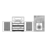
Exploded view and parts list for the exterior components of the audio system.

Cassette Mechanism Module Exploded View

Schematic Diagrams

Overall Connection Diagram Guide

General overview of the unit's connection diagram, serving as a guide.

FM/AM Tuner Unit Schematic Diagram

Cassette Mechanism Module Schematic Diagram

PCB Connection Diagrams

Main Unit PCB Connection Diagram

PCB connection diagram for the main unit, detailing component placement and connections.

FM/AM Tuner Unit PCB Layout

Keyboard Unit PCB Layout Diagram

Volume Assembly PCB Layout Diagram

Cassette Mechanism Module PCB Layout

Electrical Parts List

Adjustment Procedures

Tuner and Audio Adjustment Guide

Detailed connection diagram and steps for tuner and audio system adjustments.

Test Mode Operations

Motor Antenna Control Logic

DSP Amplifier Service Mode

IC Components Overview

Display Unit Connection Diagram

Diagnosis Modes Operation

Physical Address Assignment Table

Table detailing the physical address assignment for various system devices.

Diagnostic Code Assignment

Explanation of diagnostic codes specific to devices and common troubleshooting codes.

Disassembly Instructions

Connector Function Descriptions

System Explanation and Block Diagram

System Block Diagram Overview

Block diagram illustrating the overall system architecture and component interactions.

Operations Guide

Radio, Tape, and CD Operations

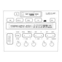
Step-by-step guide for operating the radio, tape, and CD functions.

System Specifications

Related product manuals