EasyManua.ls Logo

Pioneer M-L11 User Manual

Pioneer M-L11
26 pages
To Next Page IconTo Next Page
Page #1 background imageLoading...
Page #1 background image
ORDER NO.
PIONEER CORPORATION 4-1, Meguro 1-chome, Meguro-ku, Tokyo 153-8654, Japan
PIONEER ELECTRONICS SERVICE, INC. P.O. Box 1760, Long Beach, CA 90801-1760, U.S.A.
PIONEER EUROPE NV Haven 1087, Keetberglaan 1, 9120 Melsele, Belgium
PIONEER ELECTRONICS ASIACENTRE PTE. LTD. 253 Alexandra Road, #04-01, Singapore 159936
PIONEER CORPORATION 2001
STEREO POWER AMPLIFIER
RRV2479
T–ZZK JULY 2001 Printed in Japan
M-L11
1. SAFETY INFORMATION.................................... 2
2. EXPLODED VIEWS AND PARTS LIST ............. 3
3. BLOCK DIAGRAM AND SCHEMATIC DIAGRAM
......................................................... 8
4. PCB CONNECTION DIAGRAM ....................... 14
5. PCB PARTS LIST ............................................. 20
6. ADJUSTMENT.................................................. 22
CONTENTS
7. GENERAL INFORMATION .............................. 23
7.1 DIAGNOSIS ................................................ 23
7.1.1 DISASSEMBLY ................................. 23
7.1.2 SINGLE OPERATION METHOD ...... 24
8. PANEL FACILITIES AND SPECIFICATIONS
.................................................................... 26
MYXJ AC220–230V
NVXJ AC230V
THIS MANUAL IS APPLICABLE TO THE FOLLOWING MODEL(S) AND TYPE(S).
RemarksPower RequirementType
Model
M-L11
This product is a system(s) component.
This product does not function properly independently ; to avoid malfunctions, be
sure to connect it to the prescribed system component(s), otherwise damage may
result.
Please connect it to the STEREO CD TUNER XC-L11, for adjustment and operation
inspection.
Component Model Service manual Remarks
STEREO CD TUNER XC-L11 RRV2470
STEREO POWER AMPLIFIER M-L11 RRV2479 This manual.
SPEAKER SYSTEM S-L11-Q-LRW S-L11-S-LRW RRV2483, RRV2484
STEREO CASSETTE DECK CT-L11 RRV2471
MINIDISC RECORDER MJ-L11 RRV2472
w
w
w
.
x
i
a
o
y
u
1
6
3
.
c
o
m
Q
Q
3
7
6
3
1
5
1
5
0
9
9
2
8
9
4
2
9
8
T
E
L
1
3
9
4
2
2
9
6
5
1
3
9
9
2
8
9
4
2
9
8
0
5
1
5
1
3
6
7
3
Q
Q
TEL 13942296513 QQ 376315150 892498299
http://www.xiaoyu163.com
Question and Answer IconNeed help?

Do you have a question about the Pioneer M-L11 and is the answer not in the manual?

Pioneer M-L11 Specifications

Power IconPower
continuous power RMS satellite30 W + 30 W
continuous power RMS subwoofer50 W
continuous power DIN satellite23 W + 23 W
continuous power DIN subwoofer43 W
power requirements Europe modelAC 220-230 V, 50/60 Hz
power requirements UK modelAC 230 V, 50/60 Hz
power consumption102 W
power consumption in standby mode0.9 W
Operating Environment IconOperating Environment
temperature range+5°C to +35°C
humidity range5% to 85% (without condensation)
Weight and Dimensions IconWeight and Dimensions
dimensions190 (W) x 80 (H) x 267 (D) mm
weight4.0 kg

Summary

Safety Information

Lithium Battery Notice

Safety warning regarding lithium battery handling, replacement, and disposal.

Exploded Views and Parts List

Packing Details

Details on the packing components and lists for the product.

Exterior Components

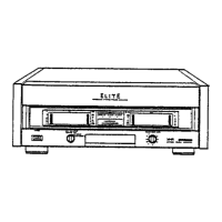
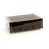
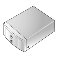
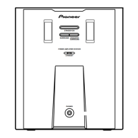
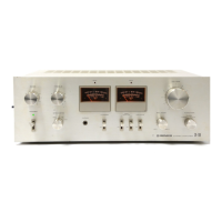
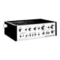
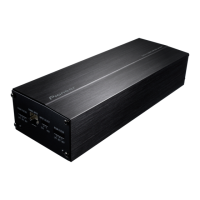
Illustrates the external parts and their arrangement on the product.

Heat Sink Assembly

Diagram and parts list for the heat sink assembly.

Block Diagram and Schematic Diagrams

Overall Connection Diagram

Shows interconnections between main assemblies and signal routes.

AC Input, Primary, Secondary Assemblies

Schematics for AC power input and associated primary/secondary circuits.

Regulation, HP, LED Assemblies

Schematics for voltage regulation, headphone, and LED driver circuits.

Amplifier and Complex Assemblies

Schematics for the amplifier and complex control assemblies.

PCB Connection Diagrams

AC/Primary/Secondary PCB Layout

PCB connection diagrams for AC input, primary, and secondary circuits.

Complex/Amp/Reg/HP/LED PCB Layout

PCB connection diagrams for complex, amplifier, regulator, HP, and LED circuits.

PCB Parts List

General Information

Diagnosis Procedures

Procedures for diagnosing faults, including disassembly steps.

Single Operation Method

Methodology for testing ICs using single operation checks.

Panel Facilities and Specifications

Panel Facilities Overview

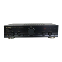
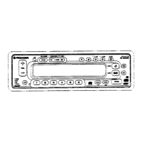
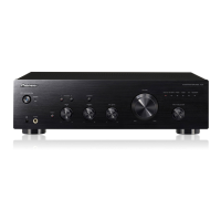
Description of the front panel controls and indicators.

Product Specifications

Technical specifications including power output, requirements, and dimensions.

Related product manuals