Do you have a question about the Pioneer PD-F1005 and is the answer not in the manual?
General warnings, laser safety, label checks, and handling precautions.
Details on leakage current checks and product safety notices for technicians.
Details differences in components for various board assemblies across models.
Compares part numbers and construction for various board assemblies across models.
Guidelines for interpreting schematic diagrams, component notations, and symbols.
Guidelines for interpreting PCB diagrams and comparing them with schematics.
Visual representation of various PCB layouts, including Loading Mechanism and Load SW Board.
Step-by-step instructions for removing the loading mechanism assembly.
Procedures for removing the operation panel and the disc rack.
Steps for removing the hood, hood base, and related components.
Instructions and diagrams for packing the product.
List of parts with their corresponding mark numbers and part numbers.
Diagram showing exterior parts and their assembly locations.
Detailed exploded view of the loading mechanism assembly.
Comprehensive list of parts with mark numbers and corresponding part numbers.
Block diagram illustrating the system control µ COM and its connections.
Detailed schematic diagrams for the main and power board assemblies.
Visual representation of various PCB layouts, including Loading Mechanism and Load SW Board.
Examples of waveforms measured at specific test points for diagnostics.
List of semiconductor parts used on various PCBs with their respective part numbers.
List of capacitors and coils with part numbers for different board assemblies.
List of resistors and switches with part numbers for various PCBs.
Pin assignment details for the FL tube on the display board.
Assignment of anode grids for character segments on the FL tube.
Identifies points requiring adjustment upon component exchange (Pickup, CD Assy, Servo Mech, Spindle Motor).
Procedures for starting and canceling test modes for adjustments.
Procedures for adjusting Focus and Tracking Servo Loop Gain.
Pin assignment and function for the PD4718A IC on the Main Board.
Detailed list of pin functions for the PD4718A IC.
Step-by-step flow chart detailing the operation sequence when the unit is powered on.
Procedure for accessing and viewing error history in test mode.
Detailed explanations of user display error codes and their meanings.
Identification and function of buttons and indicators on the front panel.
Explains the meaning of indicator lights during different operational modes.
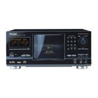
General information about the device, including type, power requirements, and dimensions.
Technical specifications related to the audio performance of the device.
Lists output terminals and included accessories with their descriptions.
| Type | CD Player |
|---|---|
| Frequency Response | 2 Hz - 20 kHz |
| Dynamic Range | 100 dB |
| Line Output Voltage | 2V |
| Channels | 2 |
| Digital outputs | Optical |