PD-F958, PD-F908
10
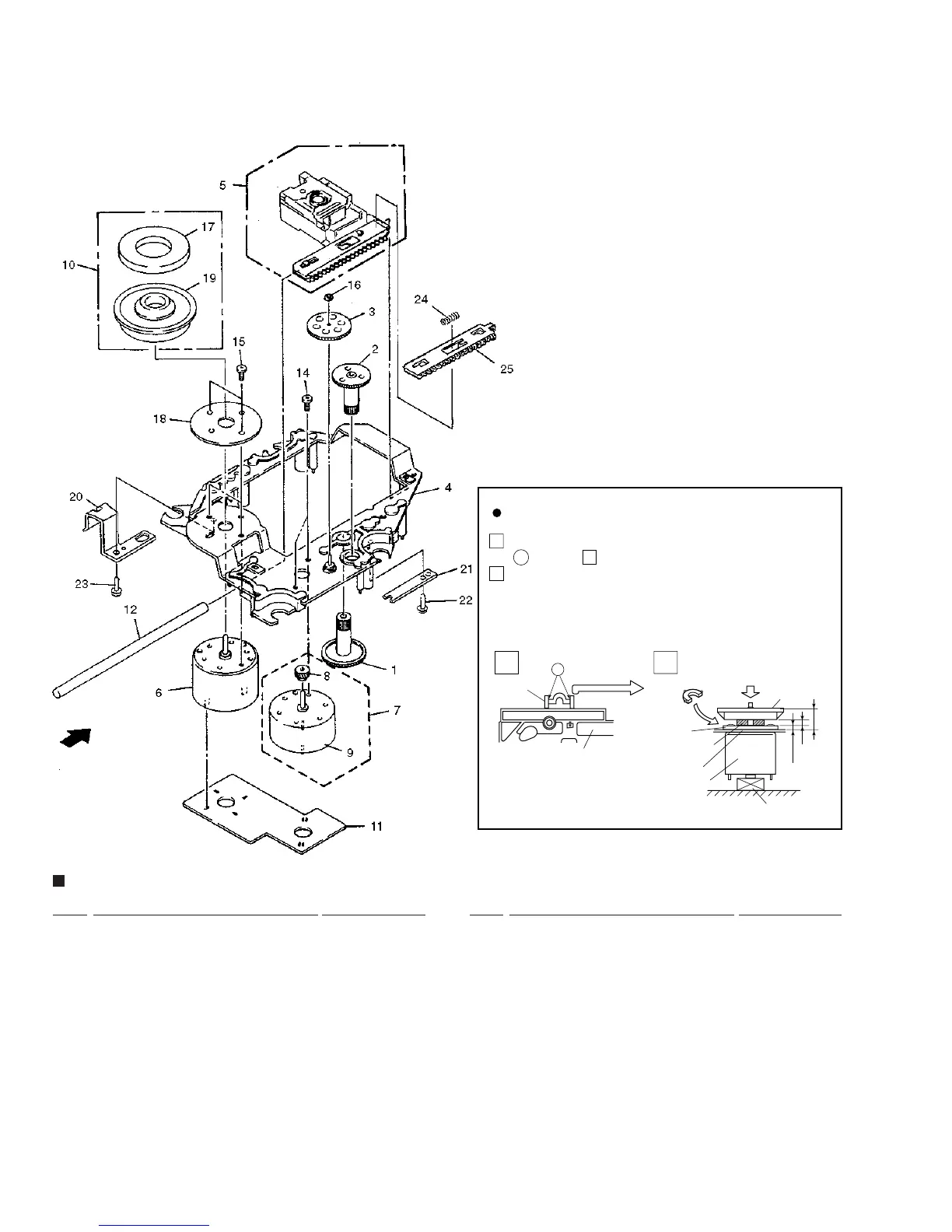
Mark No. Description Part No.
1 Gear 1 PNW2052
2 Gear 2 PNW2053
3 Gear 3 PNW2054
4 Carriage Base PNW2699
5 Pickup Assy - S PEA1335
6 D.C. Motor Assy (SPINDLE) PEA1235
7 Carriage DC Motor Assy PEA1246
8 Pinion Gear PNW2055
9 Carriage DC Motor/0.3W PXM1027
10 Disc Table Assy PEA1314
11 Mechanism Board Assy PWX1192
12 Guide Bar PLA1094
SERVO MECHANISM ASSY GM PARTS LIST
Spacer
Spacer
(Pressure of about 9 kg)
Disc Table
1.2mm
6.9mm
0.9mm
±0.05mm
Yoke M
Spindle Motor
Carriage Base
Stopper
Spacer Setting
Position
2
1
Use nipper or other tool to cut the three sections marked
in figure . Then remove the spacer
While supporting the spindle motor shaft with the
stopper, put spacer on top of the yoke M, and stick the
disc table on top (takes about 9kg pressure). Detach the
spacer.
How to Install the Disc Table
Float Base
1
1
2
A
A
2.4 SERVO MECHANISM ASSY GM
Mark No. Description Part No.
13
…………
14 Screw JFZ17P025FZK
15 Screw JFZ20P040FMC
16 Washer WT12D032D025
17 Clamp Magnet PMF1014
18 Yoke M PNB1312
NSP 19 Disc Table PNW2410
NSP 20 Float Angle ANB7020
21 Gear Stopper PNB1303
22 Screw BPZ20P060FMC
23 Screw BPZ26P100FMC
24 PU Rack Spring ABH7077
25 Rack Holder PNW2056
 Loading...