Do you have a question about the Pioneer PD-J500T and is the answer not in the manual?
Multilingual warnings and safety cautions regarding laser diode radiation exposure.
Procedure for checking labels on the twin type models for safety compliance.
Technical details including type, power, S/N ratio, and frequency response.
Note regarding potential changes to specifications and design due to improvements.
Notes regarding the availability and importance of packing parts and components.
List of parts included in the packing for product shipment.
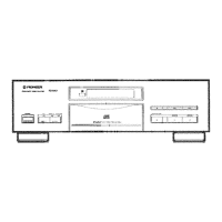
Diagrams and part numbers for the external components of the player.
Notes on part availability, supply status, and safety marking for exterior parts.
Explanation of symbols used for resistors, capacitors, voltage, current, and signals in the schematic.
Table detailing voltage measurements at specific terminals of integrated circuits.
Examples of oscilloscope waveforms at key test points for various operational modes.
Overview of PCB connections, showing major assemblies like Mother, Mechanism, Power, Connector, and Function boards.
Instructions for selecting the correct line voltage for different model types on the power board.
General notes on part ordering, availability, and safety markings for PCB components.
List of major assemblies like Mother Board, Function Board, and Power Board.
Categorized lists of semiconductors, switches, coils, transformers, and capacitors with part numbers.
List of semiconductors, capacitors, resistors, and switches for the Power Board Assembly.
List of parts for the Connector Board Assembly, including connectors and resistors.
List of parts for the Mechanism PCB Assembly, including switches and connectors.
List of semiconductors, switches, resistors, and connectors for the Function Board Assembly.
General methods, adjustment items, verification order, and required instruments for calibration.
Detailed steps for adjusting focus offset, grating, tracking balance, and pickup tilt.
Glossary of abbreviations used in the adjustment procedures for clarity.
Diagram illustrating the locations of test points and adjustment variable resistors on the main board.
Important notes regarding oscilloscope probe usage and settings for accurate adjustments.
Procedure for setting the player into test mode for service adjustments and checks.
Explanation of key functions and their operations when the player is in test mode.
Sequence of key presses required to play a disc when the player is in test mode.
Procedure to set the DC offset for the focus error amplifier for optimal performance.
Procedure to align laser beam spots to the track for optimal tracking error generation.
Procedure to correct tracking photodiode sensitivity for proper track search.
Procedure to adjust pickup angle for clear RF signal readout and optimal playback.
Procedure to optimize playback RF signal amplitude for reliable performance.
Procedure to optimize the focus servo loop gain for stable focus actuation.
Procedure to optimize the tracking servo loop gain for accurate track following.
Verification of pickup condition by observing the focus error signal waveform (S-curve).
Comparison of miscellaneous parts across different model types and configurations.
Details of parts that vary between PD-J500T/HEMXJS, HBXJS, SD and PD-J400T/HEMXJS, HBXJS, SD, HPW types.
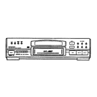
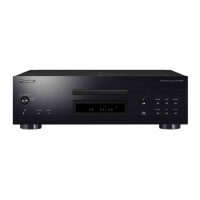
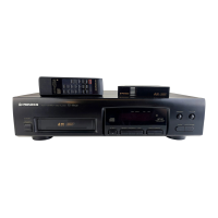
Description of the front panel layout and the functions of its controls.
Controls for power, disc tray, disc selection, and special playback modes.
Controls for playback, programming, random playback, search functions, and display.
| Type | CD Player |
|---|---|
| Frequency Response | 2 Hz - 20 kHz |
| Total Harmonic Distortion | 0.003% |
| Output Level | 2.0 V |
| Disc Capacity | 1 |
| Playback Formats | CD, CD-R |
| Digital Outputs | Coaxial, Optical |