Do you have a question about the Pioneer PL-990 and is the answer not in the manual?
Explains the turntable's integrated preamp and its utility for line-level inputs.
Details scenarios where a switch is beneficial, like vintage amp compatibility or custom preamp use.
Notes the turntable's design includes provisions for an On/Off switch on the PCB.
Guides on removing the top cover and platter to access the internal components.
Shows the PCB, highlighting the intended location for the switch and its absence.
Outlines the overall process: dismantle, jumper changes, switch installation, and reassembly.
Provides manufacturing date, origin, and model number for user reference.
Details how to detach the platter by unhooking the drive belt.
Instructions for managing movable parts like the tone arm and 45 adapter during disassembly.
Explains how to remove the turntable's bottom plastic case by unscrewing it.
Describes removing screws to gain better access to the main amplifier circuit board.
Identifies key contact points (S1, S2, S3) on the PCB relating to signal paths.
Details the removal of jumpers JR17 and JR18 that bypass the switch functionality.
Explains the process of adding jumpers (J1, J2) to connect unamplified signals.
Visual confirmation of the jumper installation for unamplified input signals.
Shows the physical installation of the new switch onto the circuit board.
Guides on reassembly and how to use the modified turntable with the new switch.
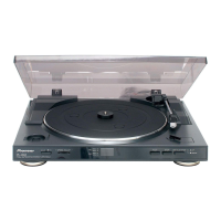
This document provides instructions for adding a PreAmp On/Off switch to a Pioneer PL-990 turntable, specifically for models manufactured around 2014. The modification allows users to bypass the turntable's built-in preamplifier, offering greater flexibility in connecting the device to various audio systems.
The Pioneer PL-990 turntable, as manufactured around 2014, includes a built-in preamplifier. This preamplifier takes the low-level signal from the turntable's cartridge and amplifies it to a "line level" signal, which is suitable for connection to standard AUX or CD inputs on an amplifier or receiver. This feature is convenient for many users as it eliminates the need for an external preamplifier.
However, for users with vintage amplifiers that typically feature a dedicated "Phono" input (designed to amplify the raw, unamplified signal from a turntable cartridge), or for those who prefer to use a different external preamplifier for potentially higher audio quality, the always-on built-in preamplifier can be a limitation. The modification described in this document addresses this by adding a switch that allows the user to enable or disable the internal preamplifier.
When the internal preamplifier is "ON," the turntable outputs a line-level signal, suitable for AUX/CD inputs. When the internal preamplifier is "OFF," the turntable outputs the raw, unamplified signal directly from the cartridge, making it suitable for connection to a "Phono" input on a vintage amplifier or an external preamplifier. This provides a choice between using the integrated preamplifier for convenience or bypassing it for compatibility with specific audio setups or for utilizing alternative amplification solutions.
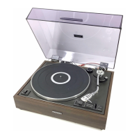
The turntable itself is a full automatic stereo turntable, meaning it handles the arm placement and return automatically, simplifying operation for the user. It supports both 33 and 45 RPM records.
The primary usage feature enabled by this modification is the ability to select between an amplified (line-level) output and an unamplified (phono-level) output from the turntable.
The switch, once installed, is located conveniently on the turntable, allowing for easy toggling between the two output modes. This enhances the versatility of the Pioneer PL-990, allowing it to seamlessly integrate into a wider range of audio setups, from modern systems to classic vintage configurations.
The turntable's existing automatic features, such as full automatic stereo operation and support for 33 and 45 RPM records, remain unchanged and fully functional regardless of the preamplifier switch setting. The modification focuses solely on the audio output path.
The document outlines a specific modification rather than general maintenance. However, the process of performing this modification inherently touches upon aspects related to the internal components and assembly of the turntable.
While not traditional maintenance, the detailed steps for accessing, modifying, and reassembling the turntable provide a framework that could be adapted for other internal maintenance tasks, such as cleaning internal components or replacing worn parts, should the need arise. The emphasis on careful handling and proper reassembly is a key takeaway for any internal work on the device.
| Type | - |
|---|---|
| Product color | Black |
| Depth | 342 mm |
|---|---|
| Width | 420 mm |
| Height | 100 mm |
| Weight | 2650 g |