EasyManua.ls Logo

Pioneer S-DVR9SW User Manual

Pioneer S-DVR9SW
42 pages
To Next Page IconTo Next Page
Page #1 background imageLoading...
Page #1 background image
ORDER NO.
PIONEER CORPORATION 4-1, Meguro 1-chome, Meguro-ku, Tokyo 153-8654, Japan
PIONEER ELECTRONICS (USA) INC. P.O. Box 1760, Long Beach, CA 90801-1760, U.S.A.
PIONEER EUROPE NV Haven 1087, Keetberglaan 1, 9120 Melsele, Belgium
PIONEER ELECTRONICS ASIACENTRE PTE. LTD. 253 Alexandra Road, #04-01, Singapore 159936
PIONEER CORPORATION 2004
S-DVR9SW
RRV3020
POWERED SUBWOOFER
S-DVR9SW
THIS MANUAL IS APPLICABLE TO THE FOLLOWING MODEL(S) AND TYPE(S).
Model Type Power Requirement Remarks
S-DVR9SW WYVXJI AC220-240V
This product does not function properly when independent ; to avoid malfunctions, be
sure to connect it to the prescribed system component(s), otherwise damage may result.
Component System
Service Manual Remarks
XV-DVR9H RRV3019
S-DVR9SW
RRV3020
RRV3021
S-DVR9ST
DVD-RW/HDD TUNER
POWERED SUBWOOFER
SPEAKER SYSTEM
This manual
For details, refer to "Important Check Points for Good Servicing".
T-ZZE SEPT. 2004 printed in Japan
Question and Answer IconNeed help?

Do you have a question about the Pioneer S-DVR9SW and is the answer not in the manual?

Pioneer S-DVR9SW Specifications

General IconGeneral
Amplifier Power100W RMS
TypeActive Subwoofer
Power Output100W
InputsLine level, speaker level
Phase Switch0° or 180°
Crossover Frequency50Hz - 200Hz

Summary

Safety Information and Precautions

Product Warnings

Mentions lead in solder and chemicals known to cause cancer, birth defects, or reproductive harm.

USA Model Safety Precautions

Outlines safety precautions for USA models, including leakage current check procedure.

Leakage Current Check Procedure

Procedure to measure leakage current to ensure product safety against shock hazards.

Product Safety Notice

Highlights the importance of using specified replacement parts for continued product safety.

Servicing Checkpoints

Product Safety in Servicing

Conforming to regulations, using specified parts, and maintaining a safe servicing environment.

Specifications

Amplifier Section Specifications

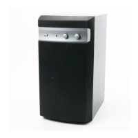
Technical specifications for the amplifier's continuous power output and performance.

Powered Subwoofer Specifications

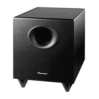
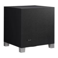
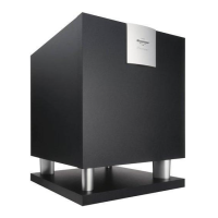
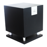
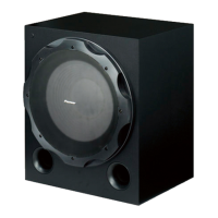
Specifications for the subwoofer enclosure, speaker, impedance, and frequency range.

Block and Schematic Diagrams

Overall System Connection Diagram

Illustrates the system block diagram and overall electrical connections between units.

AF and TRADE 1 Assembly Schematics

6CH AMP Assembly Schematic

Power and Primary Assembly Schematics

PCB Connection Diagrams

PCB Parts List

General Information

Speaker Terminal Overload Protection Diagnosis

Diagnostic procedure for protection circuit activation due to speaker terminal overload.

Power Circuit Short-Circuit Detection Diagnosis

Diagnostic procedure for short-circuit detection in the amplifier power circuit.

IC Details

BD3814FV IC Information

Details on the BD3814FV IC, including its block diagram and terminal functions.

Related product manuals