EasyManua.ls Logo

Pioneer S-W80S-J User Manual

Pioneer S-W80S-J
36 pages
To Next Page IconTo Next Page
Page #1 background imageLoading...
Page #1 background image
ORDER NO.
PIONEER CORPORATION 4-1, Meguro 1-chome, Meguro-ku, Tokyo 153-8654, Japan
PIONEER ELECTRONICS (USA) INC. P.O. Box 1760, Long Beach, CA 90801-1760, U.S.A.
PIONEER EUROPE NV Haven 1087, Keetberglaan 1, 9120 Melsele, Belgium
PIONEER ELECTRONICS ASIACENTRE PTE. LTD. 253 Alexandra Road, #04-01, Singapore 159936
PIONEER CORPORATION 2002
RRV2721
T – ZZE DEC. 2002 Printed in Japan
POWERED SPEAKER SYSTEM
S-W80S-J
Model No. Order No. Remarks
S-W80S/MLXTW RRV2591
This service manual should be used together with the following manual(s):
THIS MANUAL IS APPLICABLE TO THE FOLLOWING MODEL(S) AND TYPE(S).
Model Power Requirement Remarks
S-W80S-J AC220-230V
Type
MLXTW
Question and Answer IconNeed help?

Do you have a question about the Pioneer S-W80S-J and is the answer not in the manual?

Pioneer S-W80S-J Specifications

General IconGeneral
BrandPioneer
ModelS-W80S-J
CategorySpeaker System
LanguageEnglish

Summary

Contrast of Miscellaneous Parts

Contrast Table

Compares parts for S-W80S-J/MLXTW and S-W80S/MLXTW models.

Safety Information

Safety Precautions

Essential safety checks for customer and technician protection.

Product Safety Notice

Details on special safety-related parts and replacement component risks.

Service Symbols and Guidelines

Product Safety During Service

Conforming to regulations and maintaining safety during servicing operations.

Maintenance Adjustments

Procedures for maintaining original performance through adjustments and settings.

Cleaning Procedures

Guidance on proper cleaning of parts to restore optimal performance.

Shipping Mode and Screws

Instructions for setting shipping mode or installing screws for transit protection.

Lubricants, Glues, and Parts

Proper application of lubricants, glues, and use of specified replacement parts.

Product Specifications

Included Accessories

Lists included accessories such as speaker cords and RCA plug cords.

Exploded Views and Parts Identification

Packing Contents

Details and illustration of packing components and their order numbers.

Exterior Components

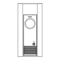
Exploded view of external parts with their corresponding part numbers.

Circuit Schematics

PCB Layout Diagrams

Jack Assembly (JACK ASSY)

PCB connection diagram for the Jack Assy, showing component placement.

Control and LED Assemblies (CNTL and LED ASSYS)

PCB connection diagrams for Control and LED assemblies.

Power and Switch Assemblies (POWER and SW. ASSYS)

PCB connection diagrams for Power and Switch assemblies.

Amplifier Assembly (AMP ASSY)

PCB connection diagram for the Amplifier (AMP) assembly.

Printed Circuit Board Parts List

General Operational Information

Disassembly Procedures

Step-by-step instructions for disassembling the amplifier, subwoofer, and front panel.

Model Identification and Differences

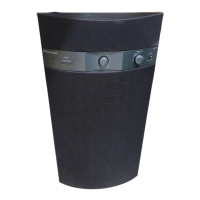
Details distinguishing between new and old models of the speaker system.

Front and Rear Panel Controls

Related product manuals