EasyManua.ls Logo

Pioneer SC-27 User Manual

Pioneer SC-27
235 pages
To Next Page IconTo Next Page
Page #1 background imageLoading...
Page #1 background image
ORDER NO.
PIONEER CORPORATION 4-1, Meguro 1-chome, Meguro-ku, Tokyo 153-8654, Japan
PIONEER ELECTRONICS (USA) INC. P.O. Box 1760, Long Beach, CA 90801-1760, U.S.A.
PIONEER EUROPE NV Haven 1087, Keetberglaan 1, 9120 Melsele, Belgium
PIONEER ELECTRONICS ASIACENTRE PTE. LTD. 253 Alexandra Road, #04-01, Singapore 159936
PIONEER CORPORATION
2009
2009 Printed in Japan
SC-27
RRV3932
AUDIO/VIDEO MULTI-CHANNEL RECEIVER
SC-27
SC-25
SC-9540
THIS MANUAL IS APPLICABLE TO THE FOLLOWING MODEL(S) AND TYPE(S).
Model Type Power Requirement Remarks
SC-27 CUXJCA AC 120 V
SC-25 CUXJCA AC 120 V
SC-9540 CUXJCA AC 120 V
For details, refer to "Important Check Points for good servicing".
T-ZZV JUNE

Table of Contents

Question and Answer IconNeed help?

Do you have a question about the Pioneer SC-27 and is the answer not in the manual?

Pioneer SC-27 Specifications

General IconGeneral
BrandPioneer
ModelSC-27
CategoryReceiver
LanguageEnglish

Summary

Service Manual

Safety Information

Safety Precautions

Essential safety guidelines for technicians and customers.

Product Safety Notice

Identifies critical safety components and replacement guidelines.

Important Check Points for Good Servicing

Product Safety

Guidelines for product safety during and after servicing.

Adjustments

Procedures for product adjustments to maintain optimal performance.

Lubricants, Glues, and Replacement parts

Guidance on using appropriate lubricants and replacement parts.

Cleaning

Instructions for cleaning components to restore performance.

Shipping mode and Shipping screws

Procedures to ensure product protection during transit.

SERVICE PRECAUTIONS

Notes on Soldering

Best practices and considerations for lead-free soldering.

Notes on Replacing Parts

Information on replacing difficult components, often requiring Assy replacement.

Caution

Critical safety notices and warnings before initiating service.

SPECIFICATIONS

Specifications

Detailed technical parameters for the receiver's various sections.

Panel Facilities

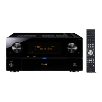
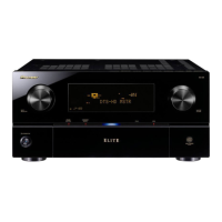
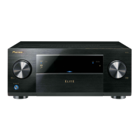
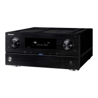
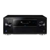
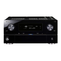
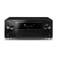
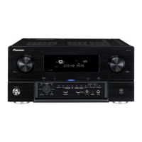
Identification and function of front panel controls and displays.

Display

Signal Indicators

Explanation of indicators for input signals and automatic signal selection.

Program Format Indicators

Indicators for PCM signal channel detection.

Digital Format Indicators

Identification of detected digital signal formats.

Rear panel

HDMI connectors

Details on multiple HDMI input and output connectors.

Component video inputs

Connection points for component video sources.

Speaker terminals

Terminals for connecting speaker systems.

AC power inlet

Connection point for the AC power cord.

Remote control

Multi-zone operation selector switch

Switch to manage operations across different zones.

Input function buttons

Buttons to select control of other components.

TV control buttons

Buttons dedicated to TV control functions.

Tuner/component control buttons/HOME MENU

Controls for tuner and components, plus access to the HOME MENU.

BASIC ITEMS FOR SERVICE

Check Points After Servicing

Essential checks to confirm after performing repairs.

Cleaning

Guidelines for cleaning the unit before shipping.

PCB Locations

Jigs List

BLOCK DIAGRAM

Overall Wiring Diagram

A comprehensive diagram illustrating the system's overall wiring connections.

Block Diagram for Audio Block

Block Diagram for Digital Video and NW Audio

Block Diagram for Analog Video Block (1/4)

Block Diagram for Analog Video Block (2/4)

Block Diagram for Analog Video Block (3/4)

Block Diagram for Analog Video Block (4/4)

Block Diagram for U-COM Block

Block Diagram for Power Block

DIAGNOSIS

Diagnosis Flowchart

A flowchart to guide troubleshooting for DSP assembly issues.

HDMI & DVC Block Troubleshooting

Step 1: Power supply

Troubleshooting steps for power supply issues related to HDMI and DVC blocks.

NW (Network) Block Troubleshooting

Step 1: Power supply

Troubleshooting steps for power supply issues within the network block.

CIRCUIT DESCRIPTION

B REG Power Supply

Description of the B REG power supply circuit and its protection mechanisms.

Amplifier Circuit

Details on amplifier protection circuits like overheat and DC detection.

Error Indications

SERVICE MODE

TEST MODE

Accessing the test mode to view detected protection history.

DISASSEMBLY

Ground Points

Identification of essential grounding points for safety during disassembly.

Screws for Rear Panel

A list of screws used for removing the rear panel.

Exterior Section

Rear panel

PCB Assys

Instructions for identifying and removing various PCB assemblies.

ICE Section

EACH SETTING AND ADJUSTMENT

HOW TO UPDATE FIRMWARE

Step-by-step guide for updating firmware via USB memory.

Network Firmware Update Procedure

Necessary Tools

Lists required tools and software for network firmware updates.

Connections

Details on how to connect the PC and AV amplifier for firmware updates.

Preparations

Procedures

Detailed steps for executing the firmware update process.

When the PC and AV amplifier are connected via a DHCP router

Specific steps for DHCP router connections, including confirming IP address.

EXPLODED VIEWS AND PARTS LIST

Packing Section

Exploded view and parts list for the product's packing contents.

Exterior Section

Rear Section

Chassis Section

Front Section

SCHEMATIC DIAGRAM

AUDIO ASSY

Schematic diagram for the audio signal processing and amplification circuits.

DSP ASSY (1/4)

DSP ASSY (2/4)

DSP ASSY (3/4)

DSP ASSY (4/4)

FRONT-HDMI ASSY

232C_CONTROL ASSY

DIGITAL MAIN ASSY (1/7)

DIGITAL MAIN ASSY (2/7)

DIGITAL MAIN ASSY (3/7)

DIGITAL MAIN ASSY (4/7)

DIGITAL MAIN ASSY (5/7)

DIGITAL MAIN ASSY (6/7)

DIGITAL MAIN ASSY (7/7)

INTERFACE ASSY

COMPONENT ASSY

COMPOSITE_S ASSY (1/2)

COMPOSITE_S ASSY (2/2)

FRONT BRIDGE, MIC HP, VOL AND POWER SW ASSYS

FRONT BRIDGE ASSY

PCB layout for the FRONT BRIDGE assembly.

MIC HP ASSY

PCB layout for the MIC HP assembly.

DISPLAY ASSY

ICE_BUFFER AND ICE SHIELD ASSYS

ICEPOWER AMP ASSY (1/5)

PRIMARY ASSY

REG ASSY

ICE_REG ASSY

B_REG ASSY

B_DIODE ASSY

HDMI RECT, H GUARD, DIGITAL_BRIDGE AND ZOUT ASSYS

HDMI RECT ASSY

PCB layout for the HDMI RECT assembly.

H GUARD ASSY

PCB layout for the H GUARD assembly.

DIGITAL BRIDGE ASSY

PCB layout for the DIGITAL BRIDGE assembly.

ZOUT ASSY

PCB layout for the ZOUT assembly.

Related product manuals