EasyManua.ls Logo

Pioneer SC-LX73 - Service Manual

Pioneer SC-LX73
18 pages
Print Icon
To Next Page IconTo Next Page
Loading...
ORDER NO.
PIONEER CORPORATION 1-1, Shin-ogura, Saiwai-ku, Kawasaki-shi, Kanagawa 212-0031, Japan
PIONEER ELECTRONICS (USA) INC. P.O. Box 1760, Long Beach, CA 90801-1760, U.S.A.
PIONEER EUROPE NV Haven 1087, Keetberglaan 1, 9120 Melsele, Belgium
PIONEER ELECTRONICS ASIACENTRE PTE. LTD. 253 Alexandra Road, #04-01, Singapore 159936
PIONEER CORPORATION
2010
2010 Printed in Japan
SC-LX83
RRV4144
AUDIO/VIDEO MULTI-CHANNEL RECEIVER
SC-LX83
SC-LX73
THIS MANUAL IS APPLICABLE TO THE FOLLOWING MODEL(S) AND TYPE(S).
This service manual should be used together with the following manual(s).
For SPECIFICATIONS and PANEL FACILITIES, refer to the operating instructions.
Model Type Porew Requirement
The voltage can be converted by the
following method.
SC-LX83 AXJ5 AC 220 V to 230 V/ 240 V With the voltage selector
SC-LX73 AXJ5 AC 220 V to 230 V/ 240 V With the voltage selector
Model No. Order No. Remarks
SC-37/UXJCB
SC-37/UXJCB
RRV4137
RRV4138 PCB RETRIEVAL DIAGRAM
K-ZZZ SEPT.

Other manuals for Pioneer SC-LX73

Question and Answer IconNeed help?

Do you have a question about the Pioneer SC-LX73 and is the answer not in the manual?

Summary

Exploded Views and Parts List

PCB Assemblies

Lists printed circuit board assemblies and their part numbers for different models.

Packing Section

Details packaging components and accessories, including cords, sheets, and cases.

Exterior Section Parts

Identifies external components such as power transformers and fuses.

Rear Section Parts

Lists components located in the rear, including tuner units and rear panels.

Chassis Section Parts

Lists chassis-related components, including fuses and internal boards.

Front Section Parts

Details front panel components like the display, power ring, and door panels.

DAC High Assembly Parts

Lists components for the DAC High assembly, noting model-specific differences.

DAC Low Assembly Parts

Lists components for the DAC Low assembly, noting model-specific differences.

Digital Main Assembly Parts

Lists components for the Digital Main assembly, noting model-specific differences.

Interface Assembly Parts

Lists components for Interface assemblies, noting model-specific differences.

Component Assembly Parts

Lists components for Component assemblies, noting model-specific differences.

Display Assembly Parts

Lists components for the Display assembly, noting model-specific differences.

Ice Buffer Assembly Parts

Lists components for the Ice Buffer assembly, noting model-specific differences.

Icepower Amplifier Assembly Parts

Lists components for the Icepower Amplifier assembly, noting model-specific differences.

Primary Assembly Parts

Lists components for the Primary assembly, noting model-specific differences.

Schematic Diagrams

DAC High Assembly Schematic

Provides the schematic diagram for the DAC High assembly, detailing circuit connections.

DAC Low Assembly Schematic

Provides the schematic diagram for the DAC Low assembly, detailing circuit connections.

Digital Main Assembly Schematic (2;10)

Presents a section of the schematic for the Digital Main assembly, showing circuit details.

Digital Main Assembly Schematic (6;10)

Presents a section of the schematic for the Digital Main assembly, showing circuit details.

Icepower Amplifier Assembly Schematic (1;5)

Presents a section of the schematic for the Icepower Amplifier assembly, showing circuit connections.

Icepower Amplifier Assembly Schematic (2;5)

Presents a section of the schematic for the Icepower Amplifier assembly, showing circuit connections.

Icepower Amplifier Assembly Schematic (3;5)

Presents a section of the schematic for the Icepower Amplifier assembly, showing circuit connections.

Icepower Amplifier Assembly Schematic (4;5)

Presents a section of the schematic for the Icepower Amplifier assembly, showing circuit connections.

Icepower Amplifier Assembly Schematic (5;5)

Presents the final section of the schematic for the Icepower Amplifier assembly.

Overview

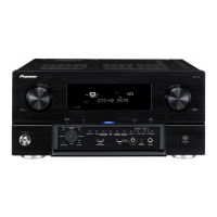
This document is a service manual for the Pioneer SC-LX83 and SC-LX73 Audio/Video Multi-Channel Receivers. It provides detailed information for technicians on the internal components, assembly, and maintenance of these devices.

The Pioneer SC-LX83 and SC-LX73 are advanced audio/video multi-channel receivers designed to deliver high-quality sound and video experiences. These receivers serve as the central hub for a home entertainment system, managing audio and video signals from various sources and distributing them to speakers and displays. Their primary function is to process and amplify audio signals for multi-channel speaker configurations, supporting immersive surround sound formats. Additionally, they handle video signal routing and processing, ensuring optimal picture quality for connected displays.

Function Description

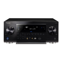
At its core, the receiver functions as an audio amplifier and a video switcher/processor. It accepts multiple audio and video inputs from sources such as Blu-ray players, gaming consoles, set-top boxes, and streaming devices. The internal circuitry then processes these signals, applying various audio decoding and video enhancement technologies.

For audio, the receiver decodes multi-channel audio formats, including advanced surround sound codecs, to create an immersive listening environment. It features multiple amplifier channels, each dedicated to driving a specific speaker in a surround sound setup (e.g., front left/right, center, surround left/right, and potentially height channels). The power requirements for these models, as indicated in the manual, are AC 220 V to 230 V/ 240 V, with a voltage selector for adaptability. This suggests a robust power supply designed to deliver clean and stable power to the amplification stages, crucial for high-fidelity audio reproduction. The presence of an "ICEPOWER AMP ASSY" (AWH7024, AWH7031, AWH7033) highlights the use of advanced Class D amplification technology, known for its efficiency and powerful output in a compact form factor.

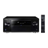
The "DAC HIGH ASSY" (AWX9622, AWX9711) and "DAC LOW ASSY" (AWX9658, AWX9659) indicate sophisticated digital-to-analog conversion stages. These are critical for converting digital audio signals from sources into analog waveforms that can be amplified by the power amplifiers. The distinction between "high" and "low" DAC assemblies might suggest different levels of performance or dedicated DACs for specific audio channels or processing paths, contributing to overall audio clarity and detail.

On the video front, the receiver acts as a central switching unit, allowing users to connect multiple video sources and select which one is sent to the display. While the manual doesn't detail specific video processing capabilities, a multi-channel receiver of this caliber would typically support high-resolution video pass-through and potentially upscaling, ensuring compatibility with modern displays and content. The "DIGITAL MAIN ASSY" (AWX9620, AWX9627, AWX9628) likely houses the primary digital signal processing (DSP) chips responsible for both audio decoding and video signal management. This assembly would coordinate the various digital operations within the receiver, from input selection to output formatting.

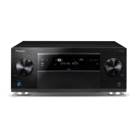
The "INTERFACE ASSY" (AWX9605, AWX9701) is responsible for managing the communication between the user and the receiver, as well as external control systems. This includes handling signals from the remote control unit and potentially network connectivity for streaming or smart home integration. The "PRIMARY ASSY" (AWX9604, AWX9697) likely contains the core control logic and power management for the entire unit, overseeing the operation of all other assemblies.

Usage Features

The design of these receivers implies a user-friendly experience, typical of Pioneer's home entertainment products. While the service manual focuses on internal components, the presence of various assemblies hints at the features available to the end-user:

  • Multi-Source Connectivity: The "DIGITAL MAIN ASSY" and "AUDIO COMPOSITE ASSY" (AWR7090, AWR7100, AWX9647, AWX9735) suggest extensive input options for both digital and analog audio/video sources. This allows users to connect a wide array of devices, from legacy equipment to modern digital components.
  • Multi-Channel Audio Support: The "ICEPOWER AMP ASSY" and dedicated DACs confirm the receiver's ability to drive complex multi-channel speaker systems, providing a true surround sound experience for movies, music, and games. The emphasis on high-quality DACs suggests a focus on audiophile-grade sound reproduction.
  • Remote Control: The "RF Remote Control Unit" (AXD7580, AXD7592) and "RF Receiver Box" (AXX7272) indicate wireless control capabilities, allowing users to operate the receiver from a distance. This enhances convenience and ease of use in a home theater setup.
  • Display and User Interface: The "PRIM_DISPLAY ASSY" (AWM8191, AWM8208, AWM8215) and "DISPLAY ASSY" (AWX9600, AWX9685, AWX9692) point to an on-screen display or a front-panel display that provides feedback to the user regarding input selection, volume levels, and other settings. This is crucial for intuitive navigation and control.
  • Tuner Functionality: The "FM/AM Tuner Unit" (AXX7267, AXX7268) allows users to listen to radio broadcasts, adding another entertainment option to the receiver's capabilities.
  • Microphone Input: The "MIC HP ICE ASSY" (AWM8190, AWM8245, AWM8244) suggests the inclusion of a microphone input, likely for features such as automatic room calibration. This feature uses a microphone to measure the acoustic properties of the listening room and automatically adjusts speaker settings for optimal sound performance.
  • Power Management: The "Power Ring" (AAK8507, AAK8477) and "Power Transformer" (ATS7430, ATS7431) indicate a robust power management system, ensuring stable operation and potentially energy-saving features.

Maintenance Features

The service manual itself is a primary maintenance feature, providing technicians with the necessary information to diagnose and repair the device. Key aspects relevant to maintenance include:

  • Detailed Parts List and Diagrams: The manual includes "EXPLODED VIEWS AND PARTS LIST" and "SCHEMATIC DIAGRAMS," which are indispensable for identifying individual components, their locations, and their interconnections. This allows for precise troubleshooting and replacement of faulty parts.
  • Contrast Tables: The "CONTRAST TABLE" sections are particularly useful, as they highlight the differences in components between the SC-LX83 and SC-LX73 models, as well as variations within the same model (e.g., different AXJ5 types). This ensures that technicians use the correct parts for the specific model being serviced.
  • Safety Information: The notes regarding "parts marked by 'NSP' are generally unavailable" and the "mark found on some component parts indicates the importance of the safety factor" emphasize critical safety considerations during repair. This guides technicians to use identical designation parts for safety-critical components, preventing potential hazards.
  • Component Identification: The detailed listing of resistors, capacitors, ICs, diodes, inductors, crystals, and connectors, along with their part numbers and descriptions, facilitates accurate component sourcing and replacement. For instance, the specific resistor codes (e.g., RS1/10SR331J, RAB4CQ470J) and capacitor codes (e.g., CKSRYB104K16, CCSSCH100D50) are provided, which are essential for ordering the correct replacement parts.
  • Assembly-Level Breakdown: The manual breaks down the receiver into logical assemblies (e.g., "AUDIO ASSY," "DAC HIGH ASSY," "DIGITAL MAIN ASSY," "ICEPOWER AMP ASSY," "INTERFACE ASSY," "DISPLAY ASSY," "ICE BUFFER ASSY," "PRIMARY ASSY"). This modular approach simplifies troubleshooting, allowing technicians to isolate problems to specific sections of the device.
  • Fuse Information: The inclusion of fuse types and ratings (e.g., "Fuse (FU13, FU14: 1A)," "Fuse (FU1: 10 A)") is crucial for diagnosing power-related issues and ensuring that replacement fuses have the correct specifications to protect the circuitry.
  • Lubricant and Glue Instructions: The note about "applying amount of lubricants or glue" indicates that specific instructions might be provided for certain assembly steps, ensuring proper mechanical function and longevity of the repaired unit.
  • Operating Instructions Reference: The statement "For SPECIFICATIONS and PANEL FACILITIES, refer to the operating instructions" directs technicians to the user manual for information not covered in the service manual, such as user-facing features and basic operation, which can be helpful for testing after repair.

In summary, the Pioneer SC-LX83 and SC-LX73 receivers are sophisticated audio/video hubs designed for high-performance home entertainment. Their internal architecture, as revealed in this service manual, emphasizes modularity, high-quality audio processing components, and robust power delivery, all supported by comprehensive documentation for effective maintenance and repair.

Pioneer SC-LX73 Specifications

General IconGeneral
BrandPioneer
ModelSC-LX73
CategoryReceiver
LanguageEnglish

Related product manuals