Do you have a question about the Pioneer SG-540 and is the answer not in the manual?
Specific warning for KU and KC models regarding the voltage selector switch functionality.
Covers essential safety guidelines for operating the appliance, including water, location, and ventilation.
Details on power cord protection, grounding, and avoiding electrical hazards like shock.
Usage of adaptor/tape terminals for connecting tape decks or external adaptors.
Information on the unswitched AC outlet and power limitations for connected equipment.
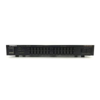
Controls the unit's power supply and indicates operational status.
Activates signal compensation via equalizer input.
Enables recording of compensated signals from equalizer.
Monitors signals from stereo components connected to tape terminals.
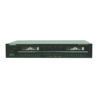
Adjusts frequency bands to boost or attenuate audio levels.
Adjusting controls to flatten frequency response peaks and dips.
Tips for adjusting controls to enhance sound quality in different room environments.
Using controls to boost or attenuate specific instrument/vocal frequencies.
Methods for reducing noise and creating compatible recorded tapes.
Step-by-step guide for playing records with equalizer adjustments.
Procedure for recording FM broadcasts using the equalizer.
Instructions for copying tapes while applying equalization.
Guidance on mixing microphone input with tape playback and recording.
Steps for recording and mixing sounds using the equalizer and a multi-mixing amplifier.
| Brand | Pioneer |
|---|---|
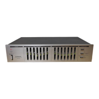
| Model | SG-540 |
| Category | Recording Equipment |
| Language | English |