EasyManua.ls Logo

Pioneer SX-4 Service Manual

Pioneer SX-4
27 pages
To Next Page IconTo Next Page
Page #1 background imageLoading...
Page #1 background image
c)ProNEEr{
2
4
6
I
I
8.
9.
10.
ORDER
NO.
ARP-O15-O
COMPUTER
CONTROLLED
STEREO RECEIVER
s)(-
MODEL
SX.4 COMES IN FOUR VERSIONS DISTINGUISHED AS
FOLLOWS:
r
This service manual is
applicable to the KU
type.
o
For
the circuit
description,
please
refer
to the model SX-7
service
manual
{ARP-047-0).
r Ce manuel d'instuction
se refdre
au mode
de r6glage, en frangais.
o Este manual
de servicio trata
del m6todo
de ajuste escrito en espafrol.
1.
2.
3.
o.
13
17
21
23
za
27
CONTENTS
SPECIFICATIONS
F
RONT
PANE
L
FACILITIES
PARTS
LOCATION
4. PACKING
BLOCK DIAGRAI\4
P.C.BOARDS
CONNECTION DIAGRAM
PIoNEEFIELECTFICINICCG,F|PCTF|AI|CTN
r-chome.M6su.o-ku.r
(,.a.
FE N--ll aLaCtFCtNlce CC,FIPC'AATIC'N 85 Oxro.ct O.'ve.
Moona.h'e,
New
Je.sey
O2O74.
u s a
PE illla tl.-CtFCtNlC IEUFC'PE, N.V. Lu'.haAe.-Haven 9.2O3o
FlCrialCF lLaCTElC'NlCa
AUaIFIALIA F Y. LYo.
1 7E' I
A4 Aolnda.y
Rodd,
B.aes'de
FHOTULY
1981
Printed
in
japan
SCHEMATIC
DIAGRAM
ELECTR ICAL PABTS
LIST .
EXPLODED
VIEW
ADJUSTMENTS
nEcuce
AJUSTE
Type
Voltag€ Remarks
KU AC 12OV only
U.S.A. model
s AC 110V, 120V,220V and 24OV
(Switchable)
General export model
KC AC 12OV only
Canada
model
YP
AC 240V only
Australia model
Question and Answer IconNeed help?

Do you have a question about the Pioneer SX-4 and is the answer not in the manual?

Pioneer SX-4 Specifications

General IconGeneral
BrandPioneer
ModelSX-4
CategoryReceiver
LanguageEnglish

Summary

Specifications

Amplifier Section

Details the performance characteristics of the audio amplifier section.

AM Tuner Section

Outlines the specifications for the AM radio tuner.

Front Panel Facilities

Power Switch

Describes the main power switch and its function.

Tuning Switch

Controls the station tuning process and frequency scanning.

FM Switch

Selects FM reception mode.

AM Switch

Selects AM reception mode.

Parts Location

Front Panel Components

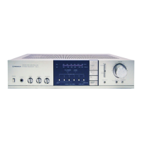
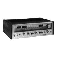
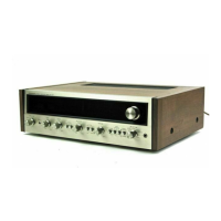
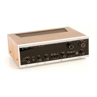
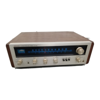
Identifies controls and indicators on the front panel.

Block Diagram

FM Front End and IF Stages

Diagram of the FM signal reception frontend circuitry.

FM MPX Stereo Demodulator

Diagram illustrating the FM stereo demodulation process.

AM Tuner and Detector

Diagram of the AM signal reception and detection stages.

Power Amplifier and Supply

Diagrams of the power amplifier and power supply circuits.

Schematic Diagram

Complex Assembly Schematic

Detailed schematic for the complex assembly.

FM Front End and IF Stages Schematic

Schematic for FM signal reception frontend and IF stages.

FM Prescaler, PLL, and Tuner Control

Schematic for FM prescaler, PLL, and tuner control functions.

Power Amplifier and Output Stages

Schematic for the power amplifier and output stages.

Electrical Parts List

Exploded View

Adjustments

Idle Current Adjustment Procedure

Details the procedure for adjusting the unit's idle current.

FM Tuner Alignment Procedures

Step-by-step guide for aligning the FM tuner.

AM Tuner Alignment Procedures

Step-by-step guide for aligning the AM tuner.

Related product manuals