Do you have a question about the Pioneer SX-316-S and is the answer not in the manual?
Details essential safety checks like leakage current and product safety notices for technicians.
Ensures safety during repairs by checking parts, soldering, connections, wiring, and environment.
Covers product adjustments, cleaning, lubricant use, and proper shipping methods.
Provides detailed technical specifications for amplifier and tuner sections, including power output and frequency ranges.
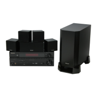
Lists the accessories provided with the unit, such as antennas, remote control, and cables.
Illustrates packing components and lists parts for shipment, including model contrast.
Diagrams of external components and their assembly, with part number references.
Diagrams of front panel components and their parts list for assembly.
Illustrates the overall signal flow and interconnections between major internal components.
Detailed schematic for the Main Assembly, covering audio processing and control circuits.
Illustrates PCB layout and component placement for Regulator and Digital In assemblies.
Shows PCB layout and component placement for Main and Front Input assemblies.
Illustrates the PCB layout and component placement for the DSP assembly.
Illustrates the PCB layout and component placement for the Power Pack assembly.
Lists main assemblies and their part numbers, detailing model variations.
Comprehensive lists of resistors and capacitors with their part numbers and locations.
Step-by-step guide for disassembling the unit, including cautions for heat sinks and component handling.
Provides guidance on diagnosing issues, including checking screws and internal component connections.
Details pin assignments and functions for ICs in the Main Assy, including System Control MCU.
Details pin assignments and functions for the IC in the Front Display Assy.
Explains DC detection, overload detection, and fan stop protection circuits and their operation.
Details XPROTECT circuit operation and a flow chart for diagnosing amplifier failures.
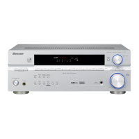
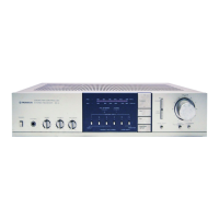
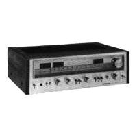
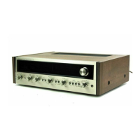
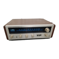
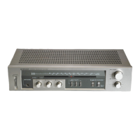
Describes the front panel layout, controls, and indicator functions for receiver operation.
Details the functions of each button on the remote control for operating the receiver and DVD/DVR.
| Type | Stereo Receiver |
|---|---|
| Total Harmonic Distortion | 0.08% |
| Inputs | 4 Audio Inputs |
| Input Sensitivity | 200mV (line) |
| Outputs | Speakers, Headphones |
| Tuning Range | FM |
| Speaker Load Impedance | 8 ohms |