Do you have a question about the Pioneer SX-727 and is the answer not in the manual?
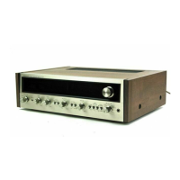
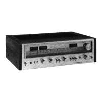
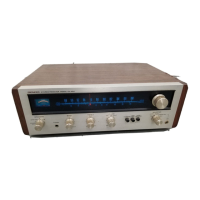
Main operational controls for adjusting sound and selecting sources.
Switches for system operation and indicators for tuning and reception status.
Ports for connecting external devices like headphones, microphones, and tape decks.
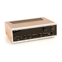
Instructions for removing the wooden case.
Procedure for removing the bottom plate.
Steps to remove the front panel assembly.
List of test equipment needed for alignment procedures.
Steps for aligning the FM intermediate frequency circuit.
Procedure for aligning the FM receiver front end stages.
Steps for aligning the FM stereo multiplex decoder circuit.
Procedure to set the FM muting threshold.
Steps for aligning the AM intermediate frequency circuit.
Procedure for aligning the AM receiver tracking.
Shows overall unit connections and lists miscellaneous components.
Detailed schematic diagram for the FM Front End circuit.
Schematic diagram for the FM/AM Tuner unit.
Schematics for the CR Unit (AWX-014 and AWX-017).
Schematic diagram for the Head Amplifier Unit.
Schematic diagram for the Audio Frequency Amplifier Unit.
Schematic diagram for the Power Amplifier Unit.
Schematic diagram for the Power Supply Unit.
Schematic diagram for the Protection Unit.
Information on Protector Unit AWM-027 replacing AWM-011 for specific serial numbers.
Notes on changes in transistors and diodes used in SX-727 design.
| Total Harmonic Distortion | 0.5% |
|---|---|
| Input Sensitivity | 2.5 mV (MM), 200 mV (line) |
| Tuning Range | FM, MW |
| Signal to Noise Ratio | 75 dB (MM), 85 dB (line) |
| Speaker Load Impedance | 4 to 16 ohms |
| Semiconductors | 4 x IC |
| Damping Factor | 40 (8 ohms, 1kHz) |