EasyManua.ls Logo

Pioneer SX-7 Service Manual

Pioneer SX-7
14 pages
To Next Page IconTo Next Page
Page #1 background imageLoading...
Page #1 background image
cDrJroNEEr{
Shot/,n tn thb
photo
b Model
SX-7.
ORDER
NO.
ARP-047-O
COMPUTER
CONTROLLED
STEREO
RECEIVER
sx-7
sx-6
SX-s.SiX-EiL
SX-,QISX-4L
.
The AM tuner of
SX-4L
wave-band tuner with MW
LW
(long
wave).
and
SX-SL is a two
(medium
wave) and
Model
SX-7
(and
SX-6, SX-5 and SX-4)
are new
types of receivers featuring microcomputers for
easier
operation. The AM/FM tuner stages incorpo-
rate
quartz
PLL
synthesizers for high stability,
while the
power
amplifier stage is a non-switching
amplifier which
achieves class A
quality
with class
B efficiency
(not
included in the
SX-4
model).
PIoNEEF| ELECTFICINTC CCtFtFCtFtATtCtN
1
chome. Mesu.o ku. rokyo 153.
J5p5n
U.a. tfcritlaF
alaC?Flo|llca CC'FFC,;|AY|C|N
a5 orro.d o. ve. Moonach e. New Je.sey
O7O74,
t)S A
FlONaaE
aL:ClFlC,l\IC
ll(rFC'PC' N.V. Lu thasen Haven
I
2O3O A..we.p
Berg'um
FroNaatl
an.actFctNlca aua?FAl-ra ETY.
LYo.
1 7a
1Ba
Bound ro. s 31
95.
aust.6r,€
F H
O
AUG.1981
Printed
in
lapan
Question and Answer IconNeed help?

Do you have a question about the Pioneer SX-7 and is the answer not in the manual?

Pioneer SX-7 Specifications

General IconGeneral
Tuning rangeFM, MW
Power Output50 watts per channel into 8Ω (stereo)
Total Harmonic Distortion0.5% (1kHz, 8 ohms)
Dimensions420 x 125 x 368.5mm
Weight9.1kg
Signal to noise ratio86dB (MM), 104dB (line)
TypeReceiver
Input Sensitivity2.5mV (MM)
Speaker load impedance4Ω to 16Ω
Speaker Impedance4Ω to 16Ω

Summary

Circuit Descriptions Overview

Outline of Main Stages

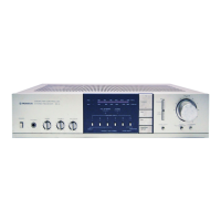
Overview of the main stages of the receiver, including tuner, amplifier, and display.

Tuner Stage Details

I.D. MOS FET in Tuner

Description of the I.D. MOS FET for improved sensitivity and reduced interference.

Pulse-Swallow PLL Synthesizer

Explanation of the pulse-swallow system for 25kHz step synthesizers.

Amplifier Stage Details

Non-Switching Amplifier Stage

Explanation of non-switching amplifier operation to suppress switching distortion.

Display Stage Features

LED Numeric Display

Description of LED numeric displays for frequency and volume control.

Signal Strength Indicator

Details on the 3-point LED SIGNAL indicator for signal strength.

Control Stage Operations

Microcomputer Control System

Overview of microcomputer ICs and system diagram for receiver control.

Function Selector Control

Description of key matrix for controlling receiver functions like PHONO, AUX, FM/AM.

Volume Control System

Details on electronic volume control IC for gain, balance, and muting.

Memory Hold Function

Explanation of RWM preservation for microcomputer data when power is off.

Related product manuals