EasyManua.ls Logo

Pioneer SX-SW77 User Manual

Pioneer SX-SW77
72 pages
To Next Page IconTo Next Page
Page #1 background imageLoading...
Page #1 background image
ORDER NO.
PIONEER CORPORATION 4-1, Meguro 1-chome, Meguro-ku, Tokyo 153-8654, Japan
PIONEER ELECTRONICS (USA) INC. P.O. Box 1760, Long Beach, CA 90801-1760, U.S.A.
PIONEER EUROPE NV Haven 1087, Keetberglaan 1, 9120 Melsele, Belgium
PIONEER ELECTRONICS ASIACENTRE PTE. LTD. 253 Alexandra Road, #04-01, Singapore 159936
PIONEER CORPORATION 2005
STANDBY/ON
-
VOLUME
+
AUDIO INPUT SURROUND
SX-SW77
RRV3158
AUDIO MULTI-CHANNEL RECEIVER SUBWOOFER
SX-SW77
SX-SW55
SX-SW950
THIS MANUAL IS APPLICABLE TO THE FOLLOWING MODEL(S) AND TYPE(S).
Model Type Power Requirement Remarks
SX-SW77 WYXCN AC220-240V
SX-SW77 WVXCN AC220-240V
SX-SW55 WYXCN AC220-240V
SX-SW55 WVXCN AC220-240V
SX-SW950 KUXCN AC120V
For details, refer to "Important Check Points for Good Servicing".
T-ZZK JUNE 2005 printed in Japan
Question and Answer IconNeed help?

Do you have a question about the Pioneer SX-SW77 and is the answer not in the manual?

Pioneer SX-SW77 Specifications

General IconGeneral
BrandPioneer
ModelSX-SW77
CategorySubwoofer
LanguageEnglish

Summary

SAFETY INFORMATION

1. SAFETY PRECAUTIONS

Outlines essential safety checks and precautions for technicians and customers.

2. PRODUCT SAFETY NOTICE

Highlights special safety characteristics of components and risks of using substitutes.

[Important Check Points for Good Servicing]

1. Product Safety

Details safety procedures, part usage, soldering, connections, and power cord safety.

2. Adjustments

Explains the importance of optimum adjustments for original product performance.

3. Lubricants, Glues, and Replacement parts

Specifies the use of correct lubricants, glues, and replacement parts.

SPECIFICATIONS

Amplifier section

Details RMS and FTC power output specifications for different channels.

FM tuner section

Specifies the frequency range and antenna type for FM tuning.

Subwoofer section

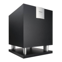
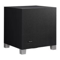
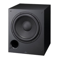
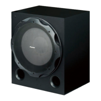
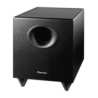
Describes the subwoofer enclosure type, system, speaker, impedance, and power.

2. EXPLODED VIEWS AND PARTS LIST

2.2 EXTERIOR

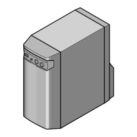
Illustrates the external parts of the unit and their numbering.

2.3 DISPLAY UNIT

Shows an exploded view of the display unit and its components.

3. BLOCK DIAGRAM AND SCHEMATIC DIAGRAM

3.1 OVERALL WIRING CONNECTION DIAGRAM AND BLOCK DIAGRAM

Shows the overall wiring connections and block diagram of the system.

3.2 MAIN ASSY (1/5)

Presents the first part of the main assembly block diagram and schematic.

3.3 MAIN ASSY (2/5)

Presents the second part of the main assembly block diagram and schematic.

3.4 MAIN ASSY (3/5)

Presents the third part of the main assembly block diagram and schematic.

3.5 MAIN ASSY (4/5)

Presents the fourth part of the main assembly block diagram and schematic.

3.6 MAIN ASSY (5/5)

Presents the fifth part of the main assembly block diagram and schematic.

3.7 AC INLET, CONNECT and FL ASSYS

Shows diagrams for AC inlet, connect, and FL assemblies.

3.8 POWER SUPPLY UNIT

Displays the block diagram and schematic for the power supply unit.

3.9 WAVEFORMS

Illustrates waveform examples relevant to the system.

5. PCB PARTS LIST

PCB Assemblies and Contrast

Lists PCB assemblies, contrast tables, and model-specific parts.

7. GENERAL INFORMATION

Diagnosis and Test Mode

Details system diagnosis, how to enter Test Mode, and its indications.

7.1.4 CIRCUIT DESCRIPTION OF DIGITAL AMP. SECTION

Power Stage section

Explains how PWM signals drive MOSFETs, including protection functions.

7.1.5 SPECIFICATIONS FOR THE PROTECTION CIRCUITS FOR THE DIGITAL AMPLIFIER

7.1.7 DISASSEMBLY

3 Speaker Disassembly

Instructions for removing the speaker from the unit.

4 Main Section Disassembly

Steps for disconnecting and removing the main internal section of the unit.

Related product manuals