Do you have a question about the Pioneer VSX-409RDS and is the answer not in the manual?
Guidelines for qualified technicians, including warnings about product safety and proper repair procedures.
Details the method for measuring leakage current to ensure product safety before customer return.
Explains how to identify safety-related components marked with 'A' for proper replacement.
Illustrates and lists parts related to product packaging, differentiating between model types.
Provides a detailed list of all components included in the product's packaging, with part numbers.
Highlights variations in packing components across different model types, referencing specific part numbers.
Lists and identifies external parts of the receiver, including chassis, covers, and panels.
Details differences in specific exterior parts (power cord, fuse) across various models.
Lists and identifies all parts associated with the front panel assembly.
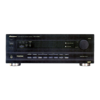
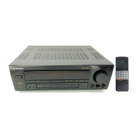
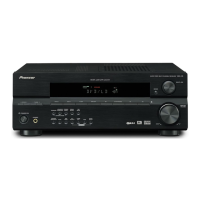
The Pioneer VSX-409RDS is an audio/video multi-channel receiver designed to serve as the central hub for a home entertainment system, integrating various audio and video sources and delivering amplified sound to loudspeakers. This service manual provides comprehensive information for qualified service technicians to maintain and repair the device, ensuring its continued optimal performance and safety.
At its core, the VSX-409RDS functions as a receiver, meaning it combines the capabilities of a preamplifier, an amplifier, and a tuner into a single unit. As a preamplifier, it takes low-level audio signals from various input sources, such as CD players, DVD players, or other audio components, and processes them before sending them to the amplifier section. This processing can include volume control, tone adjustments (bass/treble), and source selection. The amplifier section then boosts these processed signals to a level sufficient to drive passive loudspeakers, producing audible sound. The multi-channel aspect indicates its ability to handle multiple audio channels, typically for surround sound applications, allowing for an immersive listening experience with dedicated speakers for front, center, and surround channels.
Beyond basic amplification, the VSX-409RDS incorporates an audio/video switching matrix. This allows users to connect multiple audio and video sources and select which one is currently active. For instance, a user might connect a VCR, a DVD player, and a game console, and then use the receiver to switch between these sources, directing the selected audio and video signals to the appropriate output devices (e.g., a television or projector for video, and speakers for audio). The "RDS" in the model name signifies its Radio Data System capability, which is a feature of the FM/AM tuner. RDS allows the receiver to display additional information broadcast by FM radio stations, such as station name, program type, and even traffic announcements, enhancing the radio listening experience.
The receiver is designed to handle various power requirements, with different model types (MYXJIEW, MYXJIGR, MVXJI) catering to specific voltage standards (AC220-230V or AC230V). This ensures compatibility across different regions. The internal architecture includes several key assemblies: a main assembly, video and 6-channel input assembly, amplifier input assembly, amplifier and primary assembly, and a regulator assembly, all working in concert to manage signal flow, power distribution, and overall device operation. The inclusion of multiple transformers (TRANS 1, TRANS 2, TRANS 3) suggests a robust power supply design, crucial for delivering clean and stable power to the audio amplification stages, which directly impacts sound quality.
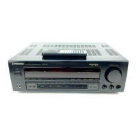
The VSX-409RDS is designed for user-friendly operation, primarily through its front panel controls and a remote control unit (AXD7243, CU-VSX167). The front panel features a volume knob for primary audio level adjustment, along with various buttons for source selection, power control, and potentially other audio processing functions. A display on the front panel provides visual feedback on the selected source, volume level, tuner information (including RDS data), and other operational parameters. This display is crucial for navigating menus and understanding the receiver's current status.
The remote control unit offers convenient operation from a distance, allowing users to adjust settings, switch sources, and control playback without needing to interact directly with the receiver. This enhances the overall user experience, especially in a home theater setup where the receiver might not be within easy reach. The inclusion of operating instructions in multiple languages (English, German, Dutch/French/Swedish, Spanish/Portuguese/Italian) indicates a broad international market focus, ensuring that users in various regions can understand and effectively utilize the device.
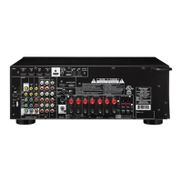
Connectivity is a key aspect of the VSX-409RDS. It provides a range of input and output terminals to accommodate diverse audio and video components. These likely include analog audio inputs (RCA jacks) for traditional stereo components, as well as multi-channel inputs for surround sound sources. Video inputs would allow connection of devices like VCRs, DVD players, and potentially game consoles. The output terminals would include speaker connections for multiple channels (front, center, surround) and potentially video outputs to connect to a television or monitor. The use of Flexible Flat Cables (FFC) for internal connections, such as between the main board and the front panel, or between the main board and the video/6-channel input board, indicates a compact and efficient internal design, minimizing clutter and optimizing signal paths.
The service manual emphasizes the importance of safety and proper maintenance for the VSX-409RDS. It is explicitly stated that the manual is intended for qualified service technicians, highlighting the complexity of the device and the need for specialized knowledge and tools for repair. This ensures that any servicing is performed correctly, preserving the product's safety and reliability.
A critical maintenance feature is the detailed breakdown of the device into various sections, including exterior, packing, exploded views, and parts lists. This systematic approach allows technicians to easily identify and locate specific components. For example, the "Exterior Section" and "Front Panel Section" provide exploded diagrams with numbered parts, each corresponding to an entry in a comprehensive parts list. This list includes part numbers and descriptions, making it straightforward to order and replace faulty components. The "Contrast Table" further refines this by highlighting differences in parts across various model types, ensuring that the correct components are used for specific regional versions of the receiver.
Safety information is paramount in the maintenance section. The manual includes "Safety Precautions" such as leakage current checks, which are vital for ensuring the electrical safety of the appliance after any repair. It specifies a maximum allowable leakage current of 0.5mA and outlines the procedure for testing, including using a leakage current tester and testing all exposed metal surfaces. This rigorous safety testing is crucial before returning the appliance to the customer.
Furthermore, the "Product Safety Notice" highlights that many electrical and mechanical parts have special safety-related characteristics, often not evident from visual inspection. These parts are identified with a "A" mark on schematics and parts lists, indicating that only PIONEER recommended replacement parts with identical safety characteristics should be used. This prevents the use of substitute components that could create shock, fire, or other hazards. The manual also stresses the continuous review of product safety and advises consulting the latest PIONEER Service Manual for updated information.
The inclusion of block diagrams and schematic diagrams (though not detailed in this excerpt, they are listed as a section in the manual) is a fundamental maintenance feature. These diagrams provide a visual representation of the internal circuitry and signal flow, allowing technicians to diagnose problems by tracing signals and identifying faulty stages. PCB connection diagrams and PCB parts lists further aid in pinpointing components on the circuit boards.
Adjustments (Section 6) are also a key maintenance feature, indicating that certain parameters within the receiver may need calibration or fine-tuning during servicing to ensure optimal performance. This could include adjustments to tuner alignment, amplifier bias, or other critical settings. Overall, the manual provides a robust framework for professional maintenance, ensuring the longevity and safe operation of the Pioneer VSX-409RDS.
| continuous power output | 80 W + 80 W (DIN, 1kHz, 0.9 %, 8 Ω) |
|---|---|
| power supply voltage | 230 V |
| power requirements | AC 220-230 V, 50/60 Hz |
| power consumption | 220 W |
| standby power consumption | 1 W |
| input sensitivity/impedance | 200 mV/47 kΩ |
|---|---|
| frequency response | 5 Hz to 100, 000 Hz |
| output level/impedance | 200 mV/2.2 kΩ |
| tone control bass | ± 6 dB (100 Hz) |
| tone control treble | ± 6 dB (10 kHz) |
| s.bass | + 8 dB (100 Hz) |
| signal-to-noise ratio | 88 dB/64 dB |
| video input sensitivity/impedance | 1 Vp-p/75 Ω |
|---|---|
| video output level/impedance | 1 Vp-p/75 Ω |
| video frequency response | 5 Hz to 7 MHz –3 dB |
| video signal-to-noise ratio | 55 dB |
| video cross talk | 55 dB |
| fm frequency range | 87.5 MHz to 108 MHz |
|---|---|
| fm usable sensitivity | Mono:15.2 dBf, IHF (1.6 µV/75 Ω) |
| fm 50 dB quieting sensitivity | Mono: 20.2 dBf |
| fm signal-to-noise ratio | Mono: 76 dB (at 85 dBf) |
| fm distortion | Stereo: 0.6 % (1 kHz) |
| fm alternate channel selectivity | 70 dB (400 kHz) |
| fm stereo separation | 40 dB (1 kHz) |
| fm frequency response | 30 Hz to 15 kHz (±1) dB |
| fm antenna input | 75 Ω unbalanced |
| fm sensitivity (DIN) | Mono: 1.1 uV(S/N 26dB) |
| fm signal-to-noise ratio (DIN) | Mono: 62dB |
| am frequency range | 531 kHz to 1, 602 kHz |
|---|---|
| am sensitivity (IHF, Loop antenna) | 350 µV/m |
| am selectivity | 30 dB |
| am signal-to-noise ratio | 50 dB |
| am antenna | Loop antenna |
| dimensions | 420 (W) x 158 (H) x 391 (D) mm |
|---|---|
| weight | 8.4 kg |