Do you have a question about the Pioneer VSX-417-K and is the answer not in the manual?
General safety guidelines for service technicians and product safety.
Procedure to measure leakage current to ensure product safety.
Notice regarding safety characteristics of electrical components and replacement parts.
Safety procedures and checks to be performed during repairs.
Procedures for optimal adjustments to maintain product performance.
Guidelines for using specified lubricants, adhesives, and replacement parts.
Proper cleaning methods for optical pickups, tape heads, and lenses.
Procedures for setting shipping mode or installing screws before shipment.
Specifications for continuous and rated power output of the amplifier section.
Input sensitivity, impedance, frequency response, and output levels for audio signals.
Specifications for bass, treble, and loudness controls.
Signal-to-noise ratio specifications for audio inputs.
Input sensitivity, impedance, and frequency response for video signals.
Frequency range, usable sensitivity, and signal-to-noise ratio for the FM tuner.
Frequency range, sensitivity, and signal-to-noise ratio for the AM tuner.
Power requirements, consumption, dimensions, and weight specifications.
List of parts provided with the unit.
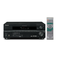
List of included accessories like antennas and remote control.
Exploded view and parts list for the packing section of the unit.
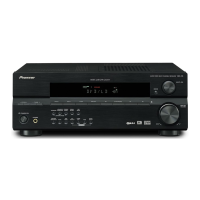
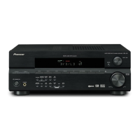
Exploded view of the unit's exterior components and their arrangement.
Exploded view of the front panel components and their layout.
Visual guide showing the location of major PCBs within the unit.
Overall block diagram illustrating the main functional units of the receiver.
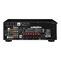
Diagram showing the interconnections between all major assemblies and components.
Schematic diagram of the Main Assembly, part 1 of 3.
Schematic diagram of the Main Assembly, part 2 of 3.
Schematic diagram of the Main Assembly, part 3 of 3.
Schematic diagram of the DSP Assembly, part 1 of 2.
Schematic diagram of the DSP Assembly, part 2 of 2.
Schematics for Power Pack (1/2), Trans2, and Trans3 Assemblies.
Schematic diagram of the Power Pack Assembly, part 2 of 2.
Schematics for Head Phone and 5.1 Channel Input Assemblies.
Schematics for Front Display, Rotary Encoder, and Power Key Assemblies.
Schematics for Trans4, Regulator, Video, Digital Input, and Primary Assemblies.
PCB connection diagram for the Digital Input Assembly (Side A and Side B).
PCB connection diagrams for the Head Phone and 5.1 Channel Input Assemblies.
PCB connection diagram for the Main Assembly.
PCB connection diagram for the DSP Assembly.
PCB connection diagrams for the Trans2 and Trans3 Assemblies.
PCB connection diagram for the Power Pack Assembly.
PCB connection diagram for the Front Display Assembly.
PCB connection diagrams for Rotary Encoder and Power Key Assemblies.
PCB connection diagrams for Trans4 and Regulator Assemblies.
PCB connection diagram for the Video Assembly.
PCB connection diagram for the Primary Assembly.
List of major assemblies and their part numbers.
List of miscellaneous ICs, diodes, and inductors with their part numbers.
List of wires and connectors for the Amp Assy.
List of jumper wires for the Complex Assy.
General information on diagnosing issues.
Flowchart for diagnosing DSP Assy issues, starting with preliminary checks.
Procedures for disassembling the unit.
General diagnostic procedures and cautions before unit disassembly.
Step-by-step guide for removing the front panel assembly of the unit.
List of integrated circuits (ICs) with their part numbers and pin assignments.
Diagrams and explanations of DC detection, overload detection, and fan stop protection circuits.
Specifications for protection circuits like DC-abnormality and overload detection.
Explanation of the XPROTECT detection process and its operation.
Describes fan stop detection and its relation to XPROTECT detection.
Illustration and explanation of the front panel controls and features.
Explanation of the various indicator lights on the front panel display.