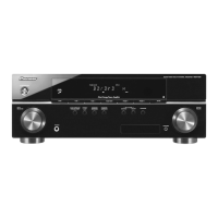
Do you have a question about the Pioneer VSX-415-K and is the answer not in the manual?
General precautions for continued protection of the customer and service technician.
Measures leakage current to earth ground to ensure product safety.
Information on safety-related characteristics of electrical components and replacement parts.
Procedures and precautions for safe servicing and product safety.
Procedures for maintaining original performance and confirming specifications.
Guidelines for using specified lubricants, glues, and replacement parts.
Procedures for cleaning parts to restore performance.
Methods for setting shipping mode or screws to prevent transit damage.
Continuous power output and tone control specifications for the amplifier.
Input/output sensitivity, impedance, and frequency response for audio.
Input/output specifications, frequency response, and signal-to-noise ratio for video.
Specifications for FM tuner frequency range, sensitivity, and signal-to-noise ratio.
Specifications for AM tuner frequency range and sensitivity.
Power requirements, consumption, dimensions, and weight specifications.
Exploded view and parts list for the product's packing.
List of exterior parts with their corresponding part numbers.
List of front panel parts with their corresponding part numbers.
Overall functional block diagram of the receiver's internal circuitry.
Diagram showing the wiring connections between different assemblies.
Schematic diagram for the first part of the Main Assembly.
Schematic diagram for the second part of the Main Assembly.
Schematic diagram for the third part of the Main Assembly.
Schematic diagram for the Digital Signal Processor (DSP) Assembly (Part 1).
Schematic diagram for the DSP Assembly (Part 2).
Schematic diagram for Amp & Primary Assembly (Part 1).
PCB connection diagram for the Regulator Assembly.
PCB connection diagram for the Amplifier Input Assembly.
PCB connection diagram for the Transistor 1 Assembly.
Schematic diagram for the Video Assembly.
Schematic diagram for the 5.1 Channel Audio Assembly.
Schematic diagram for the Front Display Assembly.
Schematic diagram for the Rotary Encoder Assembly.
Schematic diagram for the Power Switch & Key Assembly.
Schematic diagram for the Headphone (H.P.) Assembly.
Schematic diagram for the Headphone (H.P.) Assembly.
PCB connection diagram for the Transistor 3 Assembly.
PCB connection diagram for the Transistor 2 Assembly.
PCB connection diagram for the Transistor 1 Assembly.
PCB connection diagram for the Regulator Assembly.
PCB connection diagram for the Main Assembly.
PCB connection diagram for the DSP Assembly (Part 1).
PCB connection diagram for the DSP Assembly (Part 2).
PCB connection diagram for the Amplifier Input Assembly.
PCB connection diagram for the Amp & Primary Assembly.
PCB connection diagram for the Front Display Assembly.
PCB connection diagram for the Front Key Assembly.
PCB connection diagram for the Power Switch & Key Assembly.
PCB connection diagram for the Headphone (H.P.) Assembly.
PCB connection diagram for the Video Assembly.
PCB connection diagram for the 5.1 Channel Audio Assembly.
List of major assemblies with their part numbers.
List of semiconductor components with their part numbers.
List of coils and filters with their part numbers.
List of capacitors with their part numbers.
List of resistors with their part numbers.
List of other parts (connectors, crystals) with their part numbers.
General diagnosis procedures and information.
Step-by-step instructions for disassembling the unit.
List of integrated circuits (ICs) used in the system, with pin assignments.
Detailed pin functions for IC PD5963C (System Control MCU).
Detailed pin functions for IC PE5420A (Front Display IC).
Timing chart illustrating the sequence of operations during power on.
Timing chart illustrating the sequence of operations during power off.
Timing charts for data transmission between key ICs during function changes.
Circuit diagram illustrating DC detection for amplifier protection.
Circuit diagram illustrating overload detection for amplifier protection.
Circuit diagram showing PCB board protection mechanisms.
Specification for DC abnormality detection and protection sequence.
Specification for overload detection and protection sequence.
Specification for board connection error detection and protection sequence.
Flow chart for diagnosing amplifier failures based on symptoms.
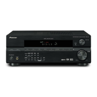
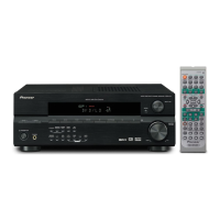
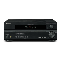
Illustration and description of the front panel controls and indicators.
Buttons used to select an input source for the receiver.
Description of the character display functionality.
Functionality and usage of the MULTI JOG dial.
Function of the STANDBY/ON button.
Purpose and usage of the PHONES jack.
Description of the MASTER VOLUME control.
Buttons to select various surround sound and decoding modes.
Use to switch between the various surround modes.
Switches between direct and stereo playback modes.
Use to select an input signal for the receiver.
Selects frequency and station presets when using the tuner.
Press to memorize and name a station for recall.
Accesses bass and treble controls adjustable with MULTI JOG.
Instructions for using the Quick Setup feature.
Illustration of the rear panel connections and ports.
Indicators for the type of input signal assigned to the current component.
Indicators for tuner mode (MONO, STEREO, TUNED).
Shows speaker system status (on/off) or headphone connection.
Indicates various settings and information on the display.
Displays the overall volume level, from minimum to maximum.
Switches the receiver between standby and on.
Buttons for selecting STANDARD, ADVANCED SURROUND, STEREO, MIDNIGHT/LOUDNESS.
Buttons for controlling receiver functions like VOLUME and MUTE.
Controls for tuning frequencies and selecting station presets.
Press to select an input source for the receiver.
| Channels | 5.1 |
|---|---|
| Total Harmonic Distortion | 0.09 % |
| Input Sensitivity | 200 mV |
| Surround System Class | 5.1 channel |
| Digital Sound Processor (DSP) | Yes |
| DSP Preset Qty | 5 |
| Tuner Bands | AM/FM |
| Inputs | 2 x Digital (1 x Optical, 1 x Coaxial) |
| Outputs | 5 x speakers output |
| Input Impedance | 47 kOhm |
| Tuner Frequency Range | FM: 87.5 - 108 MHz |
| Input Sensitivity/Impedance | 200 mV/47 kOhm |