EasyManua.ls Logo

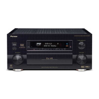
Pioneer VSX-49TXi User Manual

Pioneer VSX-49TXi
174 pages
To Next Page IconTo Next Page
Page #1 background imageLoading...
Page #1 background image
ORDER NO.
PIONEER CORPORATION 4-1, Meguro 1-chome, Meguro-ku, Tokyo 153-8654, Japan
PIONEER ELECTRONICS (USA) INC. P.O. Box 1760, Long Beach, CA 90801-1760, U.S.A.
PIONEER EUROPE NV Haven 1087, Keetberglaan 1, 9120 Melsele, Belgium
PIONEER ELECTRONICS ASIACENTRE PTE. LTD. 253 Alexandra Road, #04-01, Singapore 159936
PIONEER CORPORATION 2002
STANDBY/ON
OFF ON
STANDBY
DVD/LD TV/DVD SAT VIDEO
VIDEO AUDIO
VCR VCR2 VCR3 CD TUNER PHONO
MAC3
CD-R/
TAPE1/MD
MULTI CH
INPUT
LISTENING MODE SELECTOR
MASTER VOLUME
INPUT SELECTOR
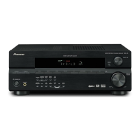
VSX-49TXi
AUDIO/VIDEO MULTI-CHANNEL AMPLIFIER
UP
DOWN
VSX-49TXi
RRV2644
AUDIO/VIDEO MULTI-CHANNEL RECEIVER
VSX-49TXi
THIS MANUAL IS APPLICABLE TO THE FOLLOWING MODEL(S) AND TYPE(S).
Model Type Power Requirement Remarks
VSX-49TXI KU/CA AC120V
For details, refer to "Important symbols for good services" .
T-ZZR AUG. 2002 printed in Japan

Table of Contents

Question and Answer IconNeed help?

Do you have a question about the Pioneer VSX-49TXi and is the answer not in the manual?

Pioneer VSX-49TXi Specifications

General IconGeneral
BrandPioneer
ModelVSX-49TXi
CategoryReceiver
LanguageEnglish

Summary

SAFETY INFORMATION

SAFETY PRECAUTIONS

Ensures continued protection of the customer and service technician.

PRODUCT SAFETY NOTICE

Highlights special safety characteristics of electrical and mechanical parts.

IMPORTANT SYMBOLS FOR GOOD SERVICES

PRODUCT SAFETY

Conform to regulations and follow safety instructions during servicing.

ADJUSTMENTS

Perform adjustments for original product performance and specification confirmation.

SPECIFICATIONS

AMPLIFIER SECTION SPECIFICATIONS

Details continuous average power output and audio section specifications.

EXPLODED VIEWS AND PARTS LIST

BLOCK DIAGRAM AND SCHEMATIC DIAGRAM

BLOCK DIAGRAM

Illustrates the overall system architecture and interconnections between major blocks.

OVERALL WIRING DIAGRAM

PCB CONNECTION DIAGRAM

PCB PARTS LIST

ADJUSTMENT

GENERAL INFORMATION

DIAGNOSIS

Provides diagnostic procedures, including test modes for checking functions.

PROTECTION CIRCUIT CONTROL

Details specifications and operation of protection circuits like fan control.

PROTECTION CIRCUIT FUNCTIONS

Details transformer temp, overload, DC detection, and diagnostic modes for unit protection.

DISASSEMBLY PROCEDURES

PARTS

INTEGRATED CIRCUITS (IC) LIST

Lists and describes the integrated circuits (ICs) used in the unit.

REMOTE CONTROL UNIT

EXPLODED VIEWS AND PARTS LIST

Provides exploded views and a parts list for the remote control unit.

REMOTE SCHEMATIC DIAGRAM

REMOTE PCB DIAGRAM

REMOTE PARTS LIST

REMOTE CONTROL OPERATION

BASIC RECEIVER CONTROL BUTTONS

Details buttons for receiver power, input selection, volume, mute, and system off functions.
Related product manuals