EasyManua.ls Logo

Pioneer VSX-504S Service Manual

Pioneer VSX-504S
52 pages
To Next Page IconTo Next Page
Page #1 background imageLoading...
Page #1 background image
Question and Answer IconNeed help?

Do you have a question about the Pioneer VSX-504S and is the answer not in the manual?

Pioneer VSX-504S Specifications

General IconGeneral
BrandPioneer
ModelVSX-504S
CategoryReceiver
LanguageEnglish

Summary

1. SAFETY INFORMATION

SAFETY PRECAUTIONS

Essential safety checks for customer and technician protection.

LEAKAGE CURRENT CHECK

Procedure to measure leakage current to earth ground.

PRODUCT SAFETY NOTICE

Details on special safety characteristics of parts and replacement.

2. EXPLODED VIEWS, PACKING AND PARTS LIST

2.1 PACKING

Details on how units are packed for shipping and comparison.

PARTS LIST FOR VSX-504S/KUXJ

List of parts for the VSX-504S/KUXJ model.

2.2 EXTERIOR

PARTS LIST FOR VSX-504S/KUXJ

Component parts list for the VSX-504S/KUXJ model.

2.3 POWER BLOCK

3. BLOCK DIAGRAM

4. SCHEMATIC AND PCB CONNECTION DIAGRAMS

4.1 OVERALL SCHEMATIC DIAGRAM

General schematic illustrating system connections and major blocks.

4.2 FM/AM TUNER MODULE

4.3 FL AND UCOM ASSY

4.4 PS AND FUNC ASSY

4.5 VOL. ASSY, TRANS ASSY, REG ASSY AND H. P. ASSY

4.6 AMP ASSY, AMP ASSY 200W AND AMP ASSY 120W

5. PCB PARTS LIST

LIST OF WHOLE PCB ASSEMBLIES

Lists all major PCB assemblies used in the various models.

FL AND UCOM ASSY PARTS

Parts list specifically for the FL and UCOM assembly.

PS AND FUNC ASSY PARTS

Component parts list for the PS and FUNC assembly.

AMP ASSY PARTS

Parts list for various AMP assemblies.

VSX-504S/KUXJ PARTS LIST

Specific parts list for the VSX-504S/KUXJ model.

6. ADJUSTMENTS

ADJUSTMENT OF FM TUNER SECTION

Procedure for adjusting the FM tuner section settings.

ADJUSTMENT OF MW TUNER SECTION

Procedure for adjusting the AM (MW) tuner section settings.

7. IC INFORMATION

PDG133A (IC902: FL AND UCOM ASSY)

Pin assignment and function details for the PDG133A micro-computer IC.

8. FL INFORMATION

FL TUBE

Information regarding the Fluorescent Display (FL) tube.

Grid Assignment

Layout of grid connections for the FL display.

Anode Connection

Details on anode connections for FL display segments.

Pin Assignment

Mapping of pins for the FL display driver.

Pin Connection

Specific pin connection details for the FL display.

9. DISASSEMBLY

9.1 PS AND FUNC ASSY

Step-by-step procedure for disassembling the PS and FUNC assembly.

9.2 POWER BLOCK

9.3 FL AND UCOM ASSY

10. REMOTE CONTROL UNIT

10.1 EXPLODED VIEW AND PARTS LIST

Exploded view and parts list for the remote control unit.

10.2 PCB PARTS LIST

10.3 PCB PATTERN

10.4 SCHEMATIC DIAGRAM

11. PANEL FACILITIES

FRONT PANEL FACILITIES

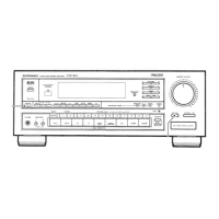
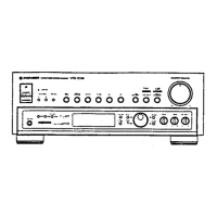
Details on front panel controls, switches, and display elements.

REAR PANEL FACILITIES

Description of rear panel input/output terminals and connections.

12. SPECIFICATIONS

VSX-504S Specifications

Technical specifications for the VSX-504S model, including amplifier, tuner, and misc.

Furnished Parts

List of parts included with the product.

Related product manuals