EasyManua.ls Logo

Pioneer VSX-515-S Service Manual

Pioneer VSX-515-S
79 pages
To Next Page IconTo Next Page
Page #1 background imageLoading...
Page #1 background image
ORDER NO.
PIONEER CORPORATION 4-1, Meguro 1-chome, Meguro-ku, Tokyo 153-8654, Japan
PIONEER ELECTRONICS (USA) INC. P.O. Box 1760, Long Beach, CA 90801-1760, U.S.A.
PIONEER EUROPE NV Haven 1087, Keetberglaan 1, 9120 Melsele, Belgium
PIONEER ELECTRONICS ASIACENTRE PTE. LTD. 253 Alexandra Road, #04-01, Singapore 159936
PIONEER CORPORATION 2005
UPDOWN
MULTI JOG
MASTER
VOLUME
ENTER
AUDIO/VIDEOMULTI-CHANNELRECEIVER
STANDBY/ON
PHONES
DVD/LD DVD 5.1 TV/SAT DVR/VCR
CD
CD-R/TAPE/MD
FM
AM
VSX-515-K
RRV3092
AUDIO/VIDEO MULTI-CHANNEL RECEIVER
VSX-515-K
VSX-515-S
THIS MANUAL IS APPLICABLE TO THE FOLLOWING MODEL(S) AND TYPE(S).
Model Type Power Requirement Remarks
VSX-515-K KUCXJ AC 120V
VSX-515-S KUCXJ AC 120V
For details, refer to "Important Check Points for Good Servicing".
ZZK MAR. 2004 printed in Japan
Question and Answer IconNeed help?

Do you have a question about the Pioneer VSX-515-S and is the answer not in the manual?

Pioneer VSX-515-S Specifications

General IconGeneral
BrandPioneer
ModelVSX-515-S
CategoryReceiver
LanguageEnglish

Summary

SAFETY INFORMATION

1. SAFETY PRECAUTIONS

Essential precautions for customer and service technician safety.

2. PRODUCT SAFETY NOTICE

Notice regarding product safety characteristics and replacement parts.

SPECIFICATIONS

Key Performance Specifications

Details on Amplifier, Audio, Video, and Component sections.

Tuner and Miscellaneous Specifications

FM/AM tuner specs, power requirements, and dimensions.

EXPLODED VIEWS AND PARTS LIST

2.1 PACKING DETAILS

Exploded view and parts list for product packing.

2.2 EXTERIOR SECTION OVERVIEW

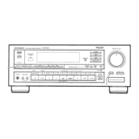
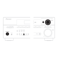
Exploded view of the exterior parts of the unit.

2.3 FRONT PANEL SECTION

Exploded view of the front panel components.

BLOCK DIAGRAM AND SCHEMATIC DIAGRAM

3.1 BLOCK DIAGRAM OVERVIEW

High-level functional block diagram of the receiver.

3.2 OVERALL WIRING CONNECTION DIAGRAM

Diagram showing overall wiring connections between assemblies.

3.3 MAIN ASSY SCHEMATICS (1/3)

Schematic diagram for the Main Assembly, part 1 of 3.

3.6 DSP ASSY SCHEMATICS (1/2)

Schematic diagram for the DSP Assembly, part 1 of 2.

PCB CONNECTION DIAGRAM

4.1 REGULATOR ASSY PCB LAYOUT

PCB layout and connection diagram for the Regulator Assembly.

4.3 MAIN ASSY PCB LAYOUT

PCB layout and connection diagram for the Main Assembly.

4.4 DSP ASSY PCB LAYOUT

PCB layout and connection diagram for the DSP Assembly.

4.7 DIGITAL IN, VIDEO, 5.1CH ASSYS PCB LAYOUT

PCB layouts for Digital In, Video, and 5.1CH Assemblies.

ELECTRICAL PARTS LIST

List of Assemblies and Semiconductor Parts

Comprehensive list of assemblies and semiconductor components.

Main Assy Component Breakdown

Detailed parts list for Main Assy semiconductors, capacitors, resistors.

Other Assembly Parts

Parts list for DSP, Camp & Primary, and other assemblies.

GENERAL INFORMATION

7.1 DIAGNOSIS AND DISASSEMBLY

Procedures for diagnosing issues and disassembling the unit.

7.2 PARTS LIST

Identification of Integrated Circuits (ICs) by part number and pinout.

7.3 EXPLANATION OF OPERATION

Detailed explanation of operational timing and detection circuits.

7.4 CLEANING PROCEDURES

Guidelines for cleaning internal components like fans.

PANEL FACILITIES

Front Panel Controls Overview

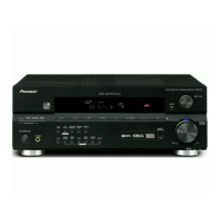
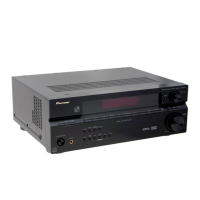
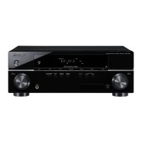
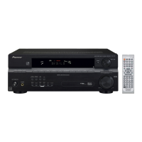
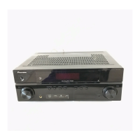
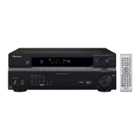
Description of buttons and indicators on the front panel.

Display Indicators Explained

Explanation of various indicators on the receiver's display.

Remote Control Functions

Detailed explanation of remote control buttons and their functions.

Related product manuals