EasyManua.ls Logo

Pioneer VSX-516-K User Manual

Pioneer VSX-516-K
124 pages
To Next Page IconTo Next Page
Page #1 background imageLoading...
Page #1 background image
ORDER NO.
PIONEER CORPORATION 4-1, Meguro 1-chome, Meguro-ku, Tokyo 153-8654, Japan
PIONEER ELECTRONICS (USA) INC. P.O. Box 1760, Long Beach, CA 90801-1760, U.S.A.
PIONEER EUROPE NV Haven 1087, Keetberglaan 1, 9120 Melsele, Belgium
PIONEER ELECTRONICS ASIACENTRE PTE. LTD. 253 Alexandra Road, #04-01, Singapore 159936
PIONEER CORPORATION 2006
UPDOWN
MULTI JOG
MASTER
VOLUME
ENTER
AUDIO/VIDEO MULTI-CHANNEL RECEIVER
VSX-516
STANDBY/ON
PHONES
DVD/LD DVD 5.1 TV/SAT
DVR/VCR
CD
CD-R/TAPE/MD
FM
AM
STANDARD
MIDNIGHT/
LOUDNESS
ADVANCED
SURR
ST/DIRECT/
AUTO SURR
LISTENING MODE
QUICK
SETUP
SETUP
RETURN
MUTE TONE
ANALOG
ATT
SPEAKERS
TUNER
EDIT
DIMMER
MULTI JOG
TUNING
STATION
SIGNAL
SELECT
SB ch
PROCESSING
DIALOGUE
ENHANCEMENT
VSX-516-K
RRV3329
AUDIO/VIDEO MULTI-CHANNEL RECEIVER
VSX-516-K
VSX-516-S
THIS MANUAL IS APPLICABLE TO THE FOLLOWINGMODEL(S) AND TYPE(S).
Model Type Power Requirement Remarks
VSX-516-K KUCXJ AC 120 V
VSX-516-S KUCXJ AC 120 V
VSX-516-K MYXJ5
AC 220 V to 230 V
VSX-516-S MYXJ5
AC 220 V to 230 V
VSX-516-S MVXJ5 AC 230 V
For details, refer to "Important Check Points for Good Servicing".
T-ZZK MAY 2006 printed in Japan
w
w
w
.
x
i
a
o
y
u
1
6
3
.
c
o
m
Q
Q
3
7
6
3
1
5
1
5
0
9
9
2
8
9
4
2
9
8
T
E
L
1
3
9
4
2
2
9
6
5
1
3
9
9
2
8
9
4
2
9
8
0
5
1
5
1
3
6
7
3
Q
Q
TEL 13942296513 QQ 376315150 892498299
http://www.xiaoyu163.com

Other manuals for Pioneer VSX-516-K

Question and Answer IconNeed help?

Do you have a question about the Pioneer VSX-516-K and is the answer not in the manual?

Pioneer VSX-516-K Specifications

General IconGeneral
BrandPioneer
ModelVSX-516-K
CategoryReceiver
LanguageEnglish

Summary

SAFETY INFORMATION

SAFETY PRECAUTIONS

Important checks for customer and technician protection.

PRODUCT SAFETY NOTICE

Special safety characteristics of electrical/mechanical parts.

1. SPECIFICATIONS

Amplifier section

Details on continuous power output, input/output, tone control, S/N ratio.

3. BLOCK DIAGRAM AND SCHEMATIC DIAGRAM

3.1 BLOCK DIAGRAM

Overall block diagram of the receiver's internal structure.

3.2 OVERALL WIRING CONNECTION DIAGRAM

Diagram showing connections between internal assemblies.

3.3 MAIN ASSY (1/3)

MAIN ASSY (1/3)

Schematic diagram for the main assembly, part 1.

3.4 MAIN ASSY (2/3)

MAIN ASSY (2/3)

Schematic diagram for the main assembly, part 2.

3.5 MAIN ASSY (3/3)

MAIN ASSY (3/3)

Schematic diagram for the main assembly, part 3.

3.6 DSP ASSY (1/2)

DSP ASSY (1/2)

Schematic diagram for the DSP assembly, part 1.

3.7 DSP ASSY (2/2)

DSP ASSY (2/2)

Schematic diagram for the DSP assembly, part 2.

3.8 POWER PACK (1/2), TRANS 2 and TRANS 3 ASSYS

POWER PACK ASSY (1/2), TRANS 2 and TRANS 3 ASSYS

Schematic diagram for power pack and transistor assemblies.

3.9 POWER PACK ASSY (2/2)

POWER PACK ASSY (2/2)

Schematic diagram for the power pack assembly, part 2.

3.10 COMPONENT ASSY

COMPONENT ASSY

Schematic diagram for the component assembly.

3.11 HEADPHONE and 5.1CHIN ASSYS

3.12 FRONT DISPLAY, R. ENCODER and POWER KEY ASSYS

3.13 TRANS 4 and REGULATOR ASSYS

3.14 VIDEO, DIGITAL IN, PRIMARY and TRANS 1 ASSYS

5. PCB PARTS LIST

LIST OF ASSEMBLIES

List of all assemblies with their part numbers.

6. ADJUSTMENT

7. GENERAL INFORMATION

7.1 DIAGNOSIS

Procedures for diagnosing potential issues within the amplifier system.

7.1.1 DISASSEMBLY

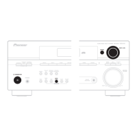
Step-by-step instructions for safely disassembling the unit.

Related product manuals