Do you have a question about the Pioneer VSX-55TXi and is the answer not in the manual?
Essential safety measures for continued customer and technician protection.
Highlights special safety characteristics of replacement components and potential hazards.
Conformance to regulations and safety during servicing.
Procedures for optimum performance and specification confirmation.
Visual representation of the receiver's functional blocks.
Comprehensive diagram showing interconnections between all major assemblies.
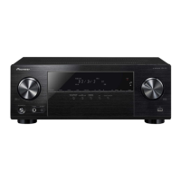
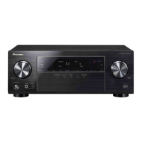
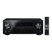
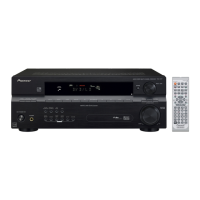
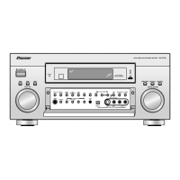
Explanation of the controls and indicators on the front panel.
Explanation of the terminals and connectors on the rear panel.
Power output and distortion specifications for the amplifier.
Input sensitivity, frequency response, and tone control specifications.
Frequency range, sensitivity, and signal-to-noise ratio for FM tuning.
| Type | AV Receiver |
|---|---|
| Channels | 7.1 |
| Input Sensitivity | 200 mV |
| DSP | Yes |
| HDMI Inputs | 3 |
| HDMI Outputs | 1 |
| Component Video Inputs | 3 |
| Component Video Outputs | 1 |
| Frequency Response | 5 Hz - 100 kHz |
| Total Harmonic Distortion (THD) | 0.09% |
| Signal-to-Noise Ratio | > 100 dB |
| Output Level | 1 V |
| Total Harmonic Distortion | < 0.08% |
| Surround Sound Formats | Dolby Digital, DTS |
| Digital Inputs | 2 optical, 2 coaxial |
| Digital Outputs | Optical: 1 |
| Analog Audio Inputs | 6 |
| Analog Audio Outputs | 1 |
| Video Inputs | 5 Composite |
| Audio Inputs | 5 |