ORDER NO.
PIONEER CORPORATION 1-1, Shin-ogura, Saiwai-ku, Kawasaki-shi, Kanagawa 212-0031, Japan
PIONEER ELECTRONICS (USA) INC. P.O. Box 1760, Long Beach, CA 90801-1760, U.S.A.
PIONEER EUROPE NV Haven 1087, Keetberglaan 1, 9120 Melsele, Belgium
PIONEER ELECTRONICS ASIACENTRE PTE. LTD. 253 Alexandra Road, #04-01, Singapore 159936
PIONEER CORPORATION
2011 Printed in Japan
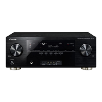
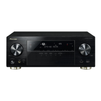
VSX-821-K
RRV4167
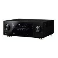
AUDIO/VIDEO MULTI-CHANNEL RECEIVER
VSX-821-K
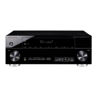
VSX-921-K
VSX-521-K
THIS MANUAL IS APPLICABLE TO THE FOLLOWING MODEL(S) AND TYPE(S).
Model Type Power Requirement Remarks
VSX-821-K CUXCNSM AC 120 V
VSX-921-K UXCNCB AC 120 V
VSX-521-K CUXCNSM AC 120 V
For details, refer to "Important Check Points for good servicing".
K-IZV MAR.