EasyManua.ls Logo

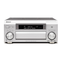
Pioneer VSX-AX4AVi-S Service Manual

Pioneer VSX-AX4AVi-S
274 pages
To Next Page IconTo Next Page
Page #1 background imageLoading...
Page #1 background image
ORDER NO.
PIONEER CORPORATION 4-1, Meguro 1-chome, Meguro-ku, Tokyo 153-8654, Japan
PIONEER ELECTRONICS (USA) INC. P.O. Box 1760, Long Beach, CA 90801-1760, U.S.A.
PIONEER EUROPE NV Haven 1087, Keetberglaan 1, 9120 Melsele, Belgium
PIONEER ELECTRONICS ASIACENTRE PTE. LTD. 253 Alexandra Road, #04-01, Singapore 159936
PIONEER CORPORATION 2005
STANDBY/ON
AUDIO/VIDEO MULTI-CHANNEL RECEIVER VSX-AX4AVi
INPUT
SELECTOR
MASTER
VOLUME
PHASE
CONTROL
MCACC
POSITION
AUTO SURR/
STREAM DIRECT
PHASE
CONTROL
DIGITAL PRECISION
PROCESSING
HOME
THX
STANDARD
SURROUND
ADVANCED
SURROUND
VSX-AX4AVi-S
RRV3261
AUDIO/VIDEO MULTI-CHANNEL RECEIVER
VSX-AX4AVi-S
VSX-AX2AV-S
THIS MANUAL IS APPLICABLE TO THE FOLLOWING MODEL(S) AND TYPE(S).
*:Alter the wiring of the power-supply block at the primary winding of Power transformer referring to the Line Voltage Selection
described in this Service Manual (“4.19 TRANS1 and PRIMARY ASSYS”).
Model Type Power Requirement
The voltage can be converted by the
following method.
VSX-AX4AVi-S HYXJ AC220-230V AC240V, *
VSX-AX2AV-S HYXJ AC220-230V AC240V, *
For details, refer to "Important Check Points for Good Servicing".
T-ZZK OCT. 2005 printed in Japan

Table of Contents

Question and Answer IconNeed help?

Do you have a question about the Pioneer VSX-AX4AVi-S and is the answer not in the manual?

Pioneer VSX-AX4AVi-S Specifications

General IconGeneral
TypeAV Receiver
Channels7.1
Frequency Response5 Hz - 100 kHz
Signal-to-Noise Ratio100 dB
Input Sensitivity200 mV
Input Impedance47 kOhms
Audio D/A Converter192 kHz/24-bit
Video ConversionYes
HDMI Inputs2
HDMI Outputs1
Component Video Inputs3
Component Video Outputs1
Digital Optical Inputs3
Digital Coaxial Inputs2
Digital Audio Inputs5
Phono InputYes
Multi-room OutputYes
THD0.09%
Surround Sound FormatsDolby Digital, DTS
Surround SoundDolby Digital, Dolby Digital EX, DTS, DTS-ES, DTS 96/24, DTS Neo:6, Dolby Pro Logic II, Dolby Pro Logic IIx

Summary

Safety Information

1. Safety Precautions

Precautions for continued protection of the customer and service technician.

2. Product Safety Notice

Electrical and mechanical parts have special safety related characteristics.

Important Check Points for Good Servicing

1. Product safety

Conform to regulations and maintain a safe servicing environment.

1. Specifications

2. Exploded Views and Parts List

2.5 Power Amp Block

3. Block Diagram and Schematic Diagram

3.1 Block Diagram

Diagrams illustrating the overall signal flow between major blocks.

3.1.1 Overall Block Diagram

High-level block diagram of the entire system.

3.1.5 DSP Block Diagram

Block diagram of the Digital Signal Processor.

3.2 Overall Wiring Connection Diagram

5. PCB Parts List

List of Assemblies

List of major assemblies with their part numbers.

7. General Information

7.1.1 Test Mode

Instructions for entering and using the test mode for version indication.

Detected Protection History

Error Indications When an Abnormality in the Amplifier System is Detected

7.1.2 Protection Circuit Specification

OL (Over Load) Detection Circuit

7.1.3 Troubleshooting the DSP Block

Simplified Diagnosis

Basic diagnosis of defective parts in the DSP Assy using main unit operations.

Troubleshooting

Step-by-step troubleshooting process for DSP block issues.

Step 7: 1st DSP

Step 8: 2nd DSP

DSP Block Diagram

CORE Block

Core functional blocks within the DSP Assy.

Power Block and GND Map

Diagram showing power supply and ground connections for the DSP Assy.

DSP Assy Check Points

7.1.4 Diagnosis of the HDMI Block and Related Systems

HDMI Simple Diagnosis

Basic troubleshooting flowchart for HDMI connectivity issues.

Status Confirmation

In a Case Where Picture is Available, but No Sound

Troubleshooting steps when audio is missing but video is present.

In a Case Where the Sound is Available, but No Picture

In a Case of No Picture and No Sound

In a Case of Abnormal Picture

Troubleshooting steps for distorted or abnormal picture quality.

Flowchart of Troubleshooting the HDMI Block

Preparations for Diagnosis of the HDMI Block and Related Systems

Diagnosis of the Video and Audio Lines Between HDMI Input and HDMI Output

Diagnosis of the Line from the Composite Video Input to the HDMI Video Output

Diagnosis of the Line from the S Video Input to the HDMI Video Output

Diagnosis of the Line from the Component Video Input to the HDMI Video Output

HDMI Troubleshooting

Step 2: Power Supply and Clock

Checking power supply and clock signals for HDMI related ICs.

Step 3: HDMI

Troubleshooting specific HDMI signal paths.

Step 3-1: Rx

Troubleshooting the receiver section of the HDMI interface.

Step 3-2: CLK, DATA

Checking clock and data signals for digital interfaces.

Step 3-3: Tx

Troubleshooting the transmitter section of the HDMI interface.

Step 4: DVC

Step 4-1: DVC

Initial checks for DVC signal path.

HDMI & DVC Assy Check Points

7.1.5 Diagnosis of the 1394 Assy

Before Making a Diagnosis

Preparatory steps before diagnosing the i.LINK interface.

i.LINK Interface

Symptoms and remedies for i.LINK audio connection issues.

Preparations for Diagnosis

1394 Assy Troubleshooting

Step 1: Connections

Checking physical connections for the 1394 Assy.

Step 2: Power Supply

Checking power supply voltages for the 1394 Assy.

1394 Assy Check Points

Operation Check of iPod Functions

7.1.7 How to Update the DSP Flash ROM by Playing Back a CD

Troubleshooting

7.1.8 How to Update the Flash ROMs for Various Microcomputers

7.1.9 Disassembly

Procedure

Step-by-step instructions for removing the Power Amp Block.

2. Disassembly

3 Replacing the Power Transistor

4 Replacing the HDMI & DVC Assy

5 Replacing the Interface Assy

INTERFACE Assy

Steps for removing the Interface Assy.

7.1.10 How to Diagnose the Product with the Power Amp Block Removed

Procedures

Step-by-step instructions for diagnosing the product with the Power Amp Block removed.

Warning: Before Putting the Power Amp Block Back

7.1.11 Failure Diagnosis of the Power Amp Block

1. Damage on the Current Amplifier Block

Diagnosing issues related to the current amplifier block.

2. Damage on the Voltage Amplifier Block

Diagnosing issues related to the voltage amplifier block.

7.2 Parts

Pin Function

PEG116A (Digital Mother Assy : IC101)

PEG118A (HDMI & DVC Assy : IC501)

PEG117A (Digital Mother Assy : IC201)

PEG116A (Digital Mother Assy : IC201)

SiI9031CTU (HDMI & DVC Assy : IC101)

SiI9030CTU (HDMI & DVC Assy : IC301)

Block Diagram

Block diagram illustrating the internal structure of the SiI9030CTU HDMI Transmitter.

Front Panel Controls and Indicators

Related product manuals