Do you have a question about the Pioneer VSX-D1011-D and is the answer not in the manual?
Crucial safety steps for technicians, including leakage current testing.
Details on special safety-related replacement parts and their identification.
Conforming to regulations and following safety instructions during servicing.
Procedures for maintaining original product performance through adjustments.
Guidelines for cleaning optical pickups, tape-deck heads, and other parts.
Setting shipping mode or installing screws to prevent transit damage.
Proper application of lubricants/glues and use of prescribed parts.
Detailed electrical specifications for the amplifier section.
Specifications for composite video inputs and outputs.
Specifications for S-Video inputs and outputs.
Specifications for component video inputs and outputs.
Performance specifications for the FM tuner.
Performance specifications for the AM tuner.
General specifications including power requirements and dimensions.
List of accessories and items included with the product.
Exploded view of the product's packing and included accessories.
List and images of included accessories like remote controls and antennas.
Exploded view of the exterior components of the unit.
Exploded view of the rear panel components.
Exploded view of the heat sink assembly and related parts.
Exploded view of the front panel components.
Block diagram illustrating the audio signal flow and circuitry.
Block diagram illustrating the digital signal processing (DSP) circuitry.
Block diagram illustrating the video signal flow and circuitry.
Block diagram of the power amplifier stages.
Diagram showing the overall wiring connections between major assemblies.
Schematic diagram of the FM/AM tuner module.
Schematic diagrams for 7.1CH I/O, V-Audio, Front In, and Optical In assemblies.
Schematic diagrams for input connect and coaxial in assemblies.
Schematic diagram of the video processing assembly.
Schematic diagrams for component video and mecha switch assemblies.
First part of the schematic for the main control assembly.
Second part of the schematic for the main control assembly.
Third part of the schematic for the main control assembly.
Schematics for MIC/F.OPT, MIC AMP, and DSP connection assemblies.
Schematics for power amp in, fan drive, and fan connection assemblies.
First part of the schematic for the DSP assembly.
Second part of the schematic for the DSP assembly.
Schematic diagram of the display assembly.
Schematics for volume, multi jog, and headphone assemblies.
Schematic diagram of the regulator assembly.
Schematic diagram of the power amplifier-L assembly.
Schematics for power amp-R and power amp-C assemblies.
Schematics for SP/PS, diode, transistor 2-1, and VH TR assemblies.
Schematics for transistor 2-2, transistor 1, and primary assemblies.
PCB connection diagram for the FM/AM tuner module.
PCB connection diagram for the 7.1 channel input/output assembly.
PCB connection diagram for the V-audio input assembly.
PCB connection diagrams for front in, optical in, and input connect assemblies.
PCB connection diagram for the coaxial input assembly.
PCB connection diagram for the video assembly.
PCB connection diagram for the main control assembly.
PCB connection diagrams for MIC/F.OPT, MIC AMP, and DSP connection assemblies.
PCB connection diagram for the power amplifier input assembly.
PCB connection diagram for the DSP assembly.
PCB connection diagrams for mecha SW, display, volume, multi jog, and headphone assemblies.
PCB connection diagrams for regulator and component assemblies.
PCB connection diagrams for power amp-L and power amp-C assemblies.
PCB connection diagram for the power amplifier-R assembly.
PCB connection diagram for the SP/PS assembly.
PCB connection diagrams for diode, transistor 2-1, and VH TR assemblies.
PCB connection diagrams for transistor 2-2, transistor 1, and primary assemblies.
Comprehensive list of all PCB assemblies and their part numbers.
Information regarding adjustments for the AM tuner section.
Adjustment procedure for the FM tuner section, including T-METER adjustment.
Details on diagnosis, protection circuits, and thermal/fan detection specifications.
Procedures for thermal detection, fan control, and fan operation.
Specifics on how the fan detection system operates and its warnings.
Explains the diagnostic mode for checking circuit design and abnormality detection.
Lists protection mechanisms, detection methods, and remarks for various failure modes.
Specific steps for diagnosing amplifier section faults and component checks.
Step-by-step troubleshooting guide for sound output issues with digital input.
Instructions for disassembling the bonnet case and heat sink block.
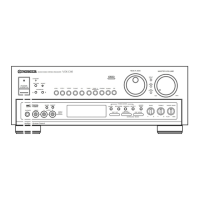
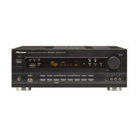
Explanation of all controls and indicators on the front panel.
Explanations of all display indicators and their meanings.
Explanation of all terminals on the rear panel and their functions.
Description of all buttons on the remote control and their operations.
| Type | AV Receiver |
|---|---|
| Input Sensitivity | 200 mV |
| Input Impedance | 47 kOhms |
| Digital inputs | coaxial, optical |
| Tuner Section | AM/FM |
| Preset Stations | 30 |
| Video Connections | Composite, S-Video |
| Audio Formats Supported | Dolby Digital, DTS |
| Video Output | 1 |
| Dimensions | 420 x 158 x 404mm |
| Power Output | 100 W per channel (8 ohms) |