Do you have a question about the Pioneer VSX-D514-K and is the answer not in the manual?
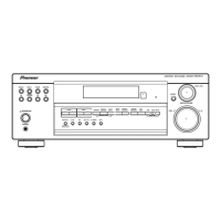
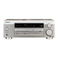
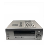
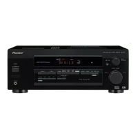
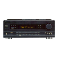
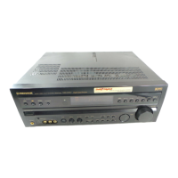
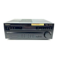
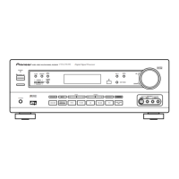
Identifies the type of audio/video equipment covered by the manual.
Covers product safety, adjustments, cleaning, shipping, and part replacement procedures.
Details safety precautions, including leakage current checks and product safety notices.
Technical specifications for the amplifier output, frequency response, and input sensitivity.
Technical specifications for video input/output, frequency response, and signal-to-noise ratio.
Technical specifications for FM tuner frequency range, sensitivity, and signal-to-noise ratio.
Technical specifications for AM tuner frequency range, sensitivity, and signal-to-noise ratio.
General specifications like power requirements, consumption, dimensions, and furnished parts.
List of parts included in the product's packing.
Diagram illustrating the packing of the product and its components.
Table showing differences in parts between VSX-D514 and VSX-D414 models for packing.
List of parts related to the exterior of the unit.
Table detailing part differences between VSX-D514 and VSX-D414 models for exterior parts.
List of parts specific to the front panel of the unit.
Table showing part variations between VSX-D514 and VSX-D414 models for front panel parts.
High-level overview of the unit's functional blocks and their interconnections.
Important notes for interpreting PCB diagrams and part identification.
Lists all PCB assemblies with their part numbers and model variations.
Diagnostic information, including timing charts for power on/off and IC data transmission.
Timing chart illustrating the sequence of operations during power on and off.
Visual representation of the pin layout for the PE5420A IC.
Detailed list of pin names, ports, and their respective functions.
Diagram illustrating the 9-channel function switch configuration.
Block diagram illustrating the internal functions of the BD3841FS IC.
Detailed listing of terminals and their descriptions for the BD3841FS IC.
Description of the 6.1ch audio sound processor function.
Block diagram of the 6.1ch audio sound processor.
Detailed listing of terminals and their descriptions for the BD3813KS IC.
Information about the XAV3022 display unit.
Specifics about the FL (Fluorescent Display) component.
Diagram showing the pin assignment of the display unit.
Grid layout for segments and characters on the display.
Detailed mapping of segments to display elements.
| Type | AV Receiver |
|---|---|
| Channels | 5.1 |
| Tuner Presets | 30 |
| Power Output | 100 W per channel |
| Frequency Response | 5 - 100000 Hz |
| Total Harmonic Distortion | 0.09% (20Hz-20kHz, 8 ohms) |
| Inputs | 1 x Optical, 1 x Coaxial |
| Outputs | 1 x Subwoofer |
| Surround Sound Formats | Dolby Digital, DTS |
| Input Sensitivity/Impedance | 200 mV / 47 kΩ |
| Speaker Impedance | 8 ohms |