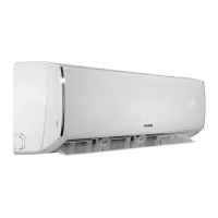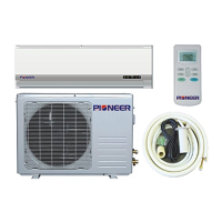
Do you have a question about the Pioneer WYE012GMFI15RL and is the answer not in the manual?
| Refrigerant | R410A |
|---|---|
| Cooling Capacity | 12000 BTU/h |
| Voltage | 208-230V |
| Power Supply | Single Phase |
| Operating Temperature | -5°C to 48°C |
General safety instructions to prevent injury and property damage during unit operation and installation.
Critical warnings regarding installation, operation, electrical safety risks, and potential hazards.
Lists specific model numbers for indoor and outdoor units based on capacity.
Identifies and labels the physical components of indoor and outdoor units.
Details the various functions and features available for the indoor and outdoor units.
Provides physical dimensions (W, D, H) for various indoor unit models.
Electrical wiring diagram for the indoor unit, showing component connections.
Electrical wiring diagram for the outdoor unit, showing component connections.
Specifies torque values for tightening fittings during installation.
Guidelines for selecting and connecting power cords based on appliance amperage.
Details maximum pipe lengths and elevation differences allowed for system installation.
Step-by-step procedure for initial air and moisture evacuation and purging.
Defines operating temperature ranges for cooling, heating, and drying modes.
Defines technical abbreviations used for sensor readings and parameters.
Explains the meaning of indicator lights and symbols on the indoor unit display.
Describes various protection mechanisms and fault conditions for the unit.
Details operation when only the fan is active, with disabled temperature control.
Explains compressor and fan running rules for cooling operation.
Describes compressor and fan running rules for heating operation.
Details protection measures against low or high evaporator coil temperatures.
Explains how the unit automatically selects cooling, heating, or fan-only based on temperature.
Describes the operation characteristics and limitations of the drying mode.
How to enter and operate the unit in forced auto or forced cooling modes.
Details the adjustable 24-hour timer functions for turning the unit on or off.
Explains the 7-hour sleep mode operation for cooling and heating cycles.
Describes the unit's ability to resume previous settings after a power failure.
Optional feature to maintain room temperature at 8°C for preventing freezing.
Lists error codes and their corresponding LED status for the indoor unit.
Describes the blue LED indicator on the outdoor PCB and its meaning for unit status.
Diagnoses and provides solutions for EEPROM parameter errors (E0/F4) involving PCB checks.
Diagnoses and resolves communication errors (E1) between indoor and outdoor units, checking wiring and PCBs.
Diagnoses and resolves zero-crossing signal errors (E2) related to PCB and connection issues.
Troubleshoots indoor fan speed errors (E3) by checking fan motor, wiring, and PCB.
Diagnoses and resolves temperature sensor errors (E5) due to open circuits, shorts, or faulty sensors.
Identifies and resolves refrigerant leakage errors (EC) by checking sensors, PCBs, and system integrity.
Addresses IPM or IGBT protection errors (P0) by checking wiring, fan, compressor, and PCBs.
Troubleshoots voltage protection errors (P1) by checking power supply, connections, and PCB.
Diagnoses and resolves compressor top high-temperature protection errors (P2) related to airflow and refrigerant.
Resolves inverter compressor drive errors (P4) by checking wiring, IPM, fan, compressor, and PCBs.
Instructions for checking the resistance of various temperature sensors using a tester.
Procedure to check IPM continuity by measuring resistance between specific terminals.
Instructions for measuring the resistance of indoor AC fan motor windings.


 Loading...