EasyManua.ls Logo

Pioneer WYE024GMFI15RL User Manual

Pioneer WYE024GMFI15RL
65 pages
To Next Page IconTo Next Page
Page #1 background imageLoading...
Page #1 background image
RevisionA:1312030001,Contentupdated.
CoolingOnlyModelNumbers(Indoor+OutdoorUnits):HeatPumpModelNumbers(Indoor+OutdoorUnits):
WAE009AMFI15RL(WE009AMFI15CLD+AN009AMFI15RPD) WYE009AMFI15RL(WE009AMFI15HLD+YN009AMFI15RPD)
WYE009GMFI15RL(WE009GMFI15HLD+YN009GMFI15RPD)
WAE012AMFI15RL(WE012AMFI15CLD+AN012AMFI15RPD) WYE012AMFI15RL(WE012AMFI15HLD+YN012AMFI15RPD)
WAE012GMFI15RL(WE012GMFI15CLD+AN012GMFI15RPD) WYE012GMFI15RL(WE012GMFI15HLD+YN012GMFI15RPD)
WAE018GMFI15RL(WE018GMFI15CLD+AN018GMFI15RPD) WYE018GMFI15RL(WE018GMFI15HLD+YN018GMFI15RPD)
WAE024GMFI15RL(WE024GMFI15CLD+AN024GMFI15RPD) WYE024GMFI15RL(WE024GMFI15HLD+YN024GMFI15RPD)
Table of Contents
1. Precaution
2. Part Names And Functions
3. Specification
4. Dimension
5. Refrigerant Cycle Diagram
6. Wiring Diagram
7. Installation Details
8. Operation Characteristics
9. Electronic Function
10. Troubleshooting
11. Exploded View
12. Disassembly Instructions
WARNING
Installation MUST conform with local building codes or, in the absence of local codes, with the
National Electrical Code NFPA70/ANSI C1-1993 or current edition and Canadian Electrical
Code Part1 CSA C.22.1.
The information contained in the manual is intended for use by a qualified service technician
familiar with safety procedures and equipped with the proper tools and test instruments.
Installation or repairs made by unqualified persons can result in hazards to you and others.
Failure to carefully read and follow all instructions in this manual can result in equipment
malfunction, property damage, personal injury and/or death.
This service
manual
is only for service engineer
'
s
to use
WAE-WYE SERIES SINGLE SPLIT DC INVERTER
AIR CONDITIONER / HEAT PUMP SYSTEMS
SERVICE MANUAL
Mono DC
Parker Davis HVAC International, Inc.
2260 NW 102nd Place, Doral, FL 33172
Ph: (305) 513-4488 info@pd-hvac.com
Question and Answer IconNeed help?

Do you have a question about the Pioneer WYE024GMFI15RL and is the answer not in the manual?

Pioneer WYE024GMFI15RL Specifications

General IconGeneral
RefrigerantR410A
Cooling Capacity24000 BTU/h
Heating Capacity24000 BTU/h
Operating Temperature (Cooling)18°C to 46°C
Operating Temperature (Heating)-15°C to 24°C

Summary

Precaution

Safety Precaution

Essential safety instructions for preventing injury and property damage during operation and installation.

Warning

Critical warnings regarding electrical hazards, installation, handling, and operational risks.

CAUTION

Important cautions for installation, operation, maintenance, and handling to prevent damage or malfunction.

Part Names And Functions

Model Names of Indoor/Outdoor units

Lists the specific model numbers for indoor and outdoor units based on capacity.

Part names of Indoor/Outdoor units

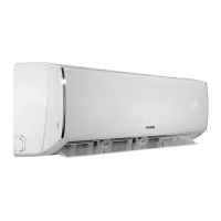
Identifies and labels the different parts of the indoor and outdoor units with diagrams.

Functions of Indoor/Outdoor units

Details the various functions and features available for the indoor and outdoor units, including optional ones.

Dimension

Indoor Unit

Specifications for indoor unit dimensions including width, depth, and height.

Refrigerant Cycle Diagram

Wiring Diagram

Indoor Unit

Detailed wiring diagram for the indoor unit, showing component connections and labels.

Outdoor Unit

Detailed wiring diagram for the outdoor unit, illustrating electrical connections and component layout.

Installation Details

Wrench torque sheet for installation

Provides torque specifications for various pipe diameters during installation.

Connecting the cables

Details the AWG wire size selection based on appliance amperage for power cord connection.

Pipe length and the elevation

Specifies maximum pipe length, elevation, and refrigerant charge per meter for different models.

Installation for the first time

Step-by-step guide for initial air and moisture evacuation and purging of the refrigerant system.

Operation Characteristics

Electronic Function

Abbreviation

Defines abbreviations used for temperature sensors (T1-T5) in the system.

Display function

Explains the icons and indicators on the indoor unit's display board for operation and error codes.

Main Protection

Details various protection mechanisms and fault detection features to safeguard the unit's operation.

Operation Modes and Functions

Describes the different operating modes (Fan, Cooling, Heating, Drying, Auto) and their specific functions.

Troubleshooting

Indoor Unit Error Display

Lists error codes displayed on the indoor unit, their causes, and corresponding LED status.

Outdoor unit error display

Describes the LED indicator on the outdoor PCB and its behavior during standby and error conditions.

Diagnosis and Solution

Provides diagnostic steps and solutions for specific error codes like E0/F4, E1, E2, E3, E5, EC, P0, P1, P2, P4.

Related product manuals