EasyManua.ls Logo

Pioneer XC-L11 Service Manual

Pioneer XC-L11
47 pages
To Next Page IconTo Next Page
Page #1 background imageLoading...
Page #1 background image
ORDER NO.
PIONEER CORPORATION 4-1, Meguro 1-chome, Meguro-ku, Tokyo 153-8654, Japan
PIONEER ELECTRONICS SERVICE, INC. P.O. Box 1760, Long Beach, CA 90801-1760, U.S.A.
PIONEER ELECTRONIC NV Haven 1087, Keetberglaan 1, 9120 Melsele, Belgium
PIONEER ELECTRONICS ASIACENTRE PTE. LTD. 253 Alexandra Road, #04-01, Singapore 159936
PIONEER CORPORATION 2001
c
XC-L11
RRV2470
1. SAFETY INFORMATION
......................................
2
2. EXPLODED VIEWS AND PARTS LIST
...............
3
3. BLOCK DIAGRAM AND SCHEMATIC DIAGRAM
...
10
4. PCB CONNECTION DIAGRAM
.........................
22
5. PCB PARTS LIST
...............................................
30
6. ADJUSTMENT
....................................................
34
CONTENTS
7. GENERAL INFORMATION
................................
37
7.1 DISASSEMBLY
............................................
37
7.2 PARTS
..........................................................
40
7.2.1 IC
............................................................
40
7.2.2 DISPLAY
.................................................
43
8. PANEL FACILITIES AND SPECIFICATIONS
.......
44
T – ZZR JUNE 2001 Printed in Japan
STEREO CD TUNER
PLAY/PAUSE
STANDBY/ON
6 OPEN/CLOSE
STOP
0
7
Type
Model
Power Requirement
XC-L11
ZVYXJ DC power supplied from other system component
THIS MANUAL IS APPLICABLE TO THE FOLLOWING MODEL(S) AND TYPE(S).
Remarks
÷ This products are component of systems. This product does not operate normally by
itself. Please connect it to the STEREO CD TUNER XC-L11 and the STEREO POWER
AMPLIFIER M-L11, for adjustment and operation inspection.
This product is a system(s) component.
Be sure to connect it to the prescribed system component(s), otherwise damage may
result.
Component Model Service manual Remarks
STEREO CD TUNER XC-L11 RRV2470 This manual.
STEREO POWER AMPLIFIER M-L11 RRV2479
SPEAKER SYSTEM S-L11-LRW –– RRV2483
–– S-L11-Q-LRW RRV2484
STEREO CASSETTE DECK CT-L11 RRV2471
MINIDISC RECORDER MJ-L11 RRV2472

Other manuals for Pioneer XC-L11

Question and Answer IconNeed help?

Do you have a question about the Pioneer XC-L11 and is the answer not in the manual?

Pioneer XC-L11 Specifications

General IconGeneral
BrandPioneer
ModelXC-L11
CategoryTuner
LanguageEnglish

Summary

Safety Information

Lithium Battery Notice

Warning about lithium battery hazards and replacement procedures.

Label Check

Details on warning labels, including laser safety.

Additional Laser Caution

Explanation of laser interlock mechanism and Class 1 laser exposure.

Exploded Views and Parts List

Packing

Lists parts related to the product's packaging and shipping.

Exterior

Exploded view and parts list for the external components.

Exterior Parts List

Detailed list of parts for the exterior of the unit.

Loading Mechanism Assy

Exploded view and parts list for the CD loading mechanism.

Loading Mechanism Assy Parts List

Detailed list of parts for the loading mechanism.

Application of Lubricant

Instructions on where and how to apply lubricant to the mechanism.

Display Unit

Exploded view and parts list for the display unit.

Display Unit Parts List

Detailed list of parts for the display unit.

Block Diagram and Schematic Diagram

Block Diagram

Shows the overall functional blocks and signal flow of the unit.

FM/AM Tuner Module

Schematic diagram for the FM/AM Tuner Module.

Mother(1/3) Assy

Schematic diagram for the Mother Assembly (Part 1 of 3).

Mother(2/3) Assy

Schematic diagram for the Mother Assembly (Part 2 of 3).

Mother(3/3), Key R, Key L and HP Assys

Schematics for Mother, Key R, Key L, and HP assemblies.

D KeyR Assy

Schematic diagram for the KEYR assembly.

E KeyL Assy

Schematic diagram for the KEYL assembly.

G FLAC Assy

Schematic diagram for the FLAC assembly.

FLDP and CNB Assys

Schematics for FLDP and CNB assemblies.

H FLDP Assy

Schematic diagram for the FLDP assembly.

I CNB Assy

Schematic diagram for the CNB assembly.

PCB Connection Diagram

FM/AM Tuner Module

PCB connection diagram for the FM/AM Tuner Module.

MOTHER, LOAB and HP ASSYS

PCB layouts for Mother, LOAB, and HP assemblies.

B MOTHER ASSY

PCB layout for the MOTHER assembly.

C LOAB ASSY

PCB layout for the LOAB assembly.

F HP ASSY

PCB layout for the HP assembly.

KEYR, KEYL and FLAC ASSYS

PCB layouts for KEYR, KEYL, and FLAC assemblies.

D KEYR ASSY

PCB layout for the KEYR assembly.

E KEYL ASSY

PCB layout for the KEYL assembly.

G FLAC ASSY

PCB layout for the FLAC assembly.

FLDP and CNB ASSYS

PCB layouts for FLDP and CNB assemblies.

H FLDP ASSY

PCB layout for the FLDP assembly.

I CNB ASSY

PCB layout for the CNB assembly.

PCB Parts List

A FM/AM Tuner Module

Parts list for the FM/AM Tuner Module.

B MOTHER ASSY

Parts list for the Mother Assembly.

G FLAC ASSY

Parts list for the FLAC assembly.

D KEYR ASSY

Parts list for the KEYR assembly.

E KEYL ASSY

Parts list for the KEYL assembly.

H FLDP ASSY

Parts list for the FLDP assembly.

CNB ASSY

Parts list for the CNB assembly.

J LOAB ASSY

Parts list for the LOAB assembly.

Adjustment

Test Mode

Details on different test modes and how to enter/exit them.

Function And Operation In CD Test Mode

Describes functions and operations within CD test mode.

Tuner Section

Procedure for adjusting the FM tuner section.

FM Tuner Section

Procedure for adjusting the FM tuner section.

General Information

Disassembly

Step-by-step guide for disassembling the unit's exterior panels.

PCB Location

Diagram showing the location of various PCB assemblies.

CD Mecha

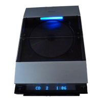
Diagram and note regarding the CD mechanism.

Display Unit

Step-by-step guide for disassembling the display unit.

Parts

List of parts for various components.

IC

Pin function details for ICs, specifically the System Control IC.

Display

Detailed pin connection and function for the FL display unit.

FL Display

Detailed pin connection and function for the FL display unit.

Panel Facilities and Specifications

Panel Facilities

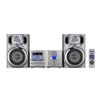
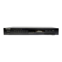
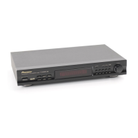
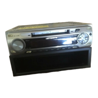
Description of the front panel controls and indicators of the CD Tuner.

Remote Control

Explanation of the functions of each button on the remote control.

Specifications

Technical specifications for the Stereo CD Tuner.

Accessories

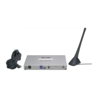
List of included accessories with the unit.

Related product manuals