ORDER NO.
PIONEER ELECTRONIC CORPORATION 4-1, Meguro 1-Chome, Meguro-ku, Tokyo 153-8654, Japan
PIONEER ELECTRONICS SERVICE, INC. P.O. Box 1760, Long Beach, CA 90801-1760, U.S.A.
PIONEER ELECTRONIC (EUROPE) N.V. Haven 1087, Keetberglaan 1, 9120 Melsele, Belgium
PIONEER ELECTRONICS ASIACENTRE PTE. LTD. 253 Alexandra Road, #04-01, Singapore 159936
PIONEER ELECTRONIC CORPORATION 1998
RRV2080
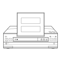
STEREO CD RECEIVER
XC-L5
1. SAFETY INFORMATION
......................................
2
2. EXPLODED VIEWS AND PARTS LIST
................
3
3. SCHEMATIC DIAGRAM
.....................................
12
4. PCB CONNECTION DIAGRAM
..........................
24
5. PCB PARTS LIST
...............................................
35
6. ADJUSTMENT
....................................................
40
CONTENTS
7. GENERAL INFORMATION
................................
43
7.1 PARTS
.........................................................
43
7.1.1 IC
.........................................................
43
7.1.2 DISPLAY
..............................................
49
7.2 DISASSEMBLY
...........................................
51
7.3 BLOCK DIAGRAM
.......................................
53
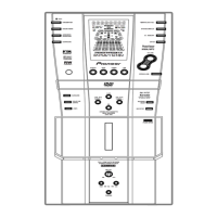
8. PANEL FACILITIES AND SPECIFICATIONS
....
54
THIS MANUAL IS APPLICABLE TO THE FOLLOWING MODEL(S) AND TYPE(S).
Type
Model
XC-L5
KUXK/CA AC120V
Power Requirement Remarks
T – ZZK DEC. 1998 Printed in Japan
AUX
STANDBY/ON
PHONES
7
06
¢4
¡
•
+–
•
1
'
VOLUME
UPDOWN
D