EasyManua.ls Logo

Pioneer XC-L77 Service Manual

Pioneer XC-L77
55 pages
To Next Page IconTo Next Page
Page #1 background imageLoading...
Page #1 background image
ORDER NO.
PIONEER CORPORATION 4-1, Meguro 1-chome, Meguro-ku, Tokyo 153-8654, Japan
PIONEER ELECTRONICS SERVICE, INC. P.O. Box 1760, Long Beach, CA 90801-1760, U.S.A.
PIONEER ELECTRONIC (EUROPE) N.V. Haven 1087, Keetberglaan 1, 9120 Melsele, Belgium
PIONEER ELECTRONICS ASIACENTRE PTE. LTD. 253 Alexandra Road, #04-01, Singapore 159936
PIONEER CORPORATION 1999
c
XC-L77
RRV2187
1. SAFETY INFORMATION
......................................
2
2. EXPLODED VIEWS AND PARTS LIST
...............
3
3. BLOCK DIAGRAM AND SCHEMATIC DIAGRAM
...
10
4. PCB CONNECTION DIAGRAM
.........................
24
5. PCB PARTS LIST
...............................................
36
6. ADJUSTMENT
....................................................
42
CONTENTS
7. GENERAL INFORMATION
................................
45
7.1 DISASSEMBLY
............................................
45
7.2 PARTS
..........................................................
48
7.2.1 IC
............................................................
48
7.2.2 DISPLAY
.................................................
51
8. PANEL FACILITIES AND SPECIFICATIONS
.......
52
T – ZZK AUG. 1999 Printed in Japan
STEREO CD RECEIVER
Type
Model
Power Requirement Remarks
XC-L77
MYXK AC220-230V
NVXK AC230V
THIS MANUAL IS APPLICABLE TO THE FOLLOWING MODEL(S) AND TYPE(S).
6
0
STANDBY/ON
PHONES
This product is a system(s) component.
Be sure to connect it to the prescribed system component(s), otherwise damage may
result.
Component Model Service manual Remarks
STEREO CD RECEIVER XC-L77 RRV2187 This manual.
S-L9-LRW RRV2176
SPEAKER SYSTEM S-L9-A-LRW RRV2176
S-L8-LRW RRV2178
STEREO CASSETTE DECK CT-L77 RRV2199
MINIDISC RECORDER MJ-L77 RRV2201
Question and Answer IconNeed help?

Do you have a question about the Pioneer XC-L77 and is the answer not in the manual?

Pioneer XC-L77 Specifications

General IconGeneral
BrandPioneer
ModelXC-L77
CategoryStereo Receiver
LanguageEnglish

Summary

Safety Information

Lithium Battery Notice

Warning and precautions for handling lithium batteries, including disposal and replacement guidelines.

Label Check

Overview of warning labels on the unit and their meanings for safe operation.

Additional Laser Caution

Details on laser safety mechanisms and precautions to avoid exposure to laser beams.

Exploded Views and Parts List

2.1 Packing

Exploded view and parts list for product packing components.

2.2 Exterior

Exploded view of the exterior components of the unit.

2.3 CD Mecha (1/2)

Exploded view and parts list for the CD mechanism (part 1).

2.4 CD Mecha (2/2)

Exploded view and parts list for the CD mechanism (part 2).

2.5 Display Unit

Exploded view and parts list for the display unit.

2.6 Remote Control Unit

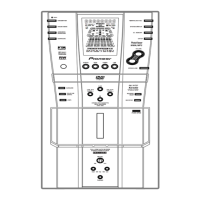
Exploded view and parts list for the remote control unit.

Block Diagram and Schematic Diagram

3.1 Block Diagram

Overall block diagram illustrating the system architecture and signal flow.

3.2 FM/AM Tuner Unit

Schematic diagram for the FM/AM tuner module.

3.3 RF and Main (1/2) Units

Schematic diagrams for RF and Main units (part 1).

3.4 Main (2/2), Keyr, Keyl, Blue Ind. and Stby SW Units

Schematics for Main, Keyr, Keyl, Blue Ind., and Stby SW units.

3.5 AMP, Woofer, Secondary, and Primary Units

Schematics for Amp, Woofer, Secondary, and Primary units.

3.6 Connector, HP and Aux Units

Schematics for Connector, HP, and Aux units.

3.7 FLSUB, Detach, Control, Terminal, Switch and FL Units

Schematics for FLSUB, DETACH, CONTROL, TERMINAL, SWITCH, and FL units.

PCB Connection Diagram

NOTE FOR PCB DIAGRAMS

Notes on comparing PCB diagrams with schematic diagrams.

4.1 FM/AM Tuner Unit

PCB layout for the FM/AM Tuner Module.

4.2 RF, Main, Keyr, Keyl, Blue Ind. and Stby SW Units

PCB layouts for RF, Main, Keyr, Keyl, Blue Ind., and Stby SW units.

4.3 AMP and SPEAKER UNITS

PCB layouts for the Amp and Speaker units.

4.4 SECONDARY and PRIMARY UNITS

PCB layouts for Secondary and Primary units.

4.5 CONNECTOR, HP and AUX UNITS

PCB layouts for Connector, HP, and Aux units.

4.6 FLSUB, DETACH, CONTROL, TERMINAL, SWITCH and FL UNITS

PCB layouts for FLSUB, DETACH, CONTROL, TERMINAL, SWITCH, and FL units.

PCB Parts List

LIST OF PCB ASSEMBLIES

Comprehensive list of PCB assemblies and their part numbers.

Adjustment

6.1 TEST MODE

Procedure for entering and exiting the test mode for adjustments.

6.1.2 FUNCTION AND OPERATION IN TEST MODE

Describes functions and operations available in test mode.

6.2 TUNER SECTION

Adjustment procedures for the FM and AM tuner sections.

General Information

7.1 Disassembly Procedures

Step-by-step guides for disassembling various unit components.

7.2 Parts Information

Detailed lists of parts, including ICs, by section.

Panel Facilities and Specifications

8.1 Panel Facilities

Description and layout of the unit's front panel controls and indicators.

8.2 Specifications

Technical specifications for the amplifier, CD player, tuner, and accessories.

Related product manuals