Do you have a question about the Pioneer XD-Z62T and is the answer not in the manual?
General safety precautions for customer and technician.
Procedure to measure leakage current of the appliance.
Important notice regarding safety characteristics of parts.
Technical specifications for the amplifier component.
Technical specifications for the tape deck component.
Technical specifications for the CD player component.
List of parts included in the packing.
Exploded views and parts list for component configurations.
Overall schematic diagram for the deck amplifier block.
Overall schematic diagram for the CD block.
Steps to change the unit's line voltage setting.
Diagram showing how to connect the unit to other devices.
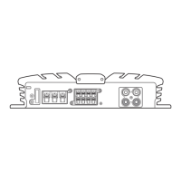
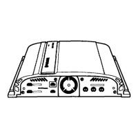
Description of the rear panel facilities.
Description of the remote control unit's functions.
Description of the front panel's amplifier section controls.
Description of the front panel's graphic equalizer controls.
Description of the front panel's cassette deck controls.
Description of the front panel's CD player controls.
Description of the TUNER jack and its connection.
Description of speaker terminals and impedance note.
Description of amplifier section front panel controls.
Description of cassette deck section front panel controls.
Exploded views and parts list for the CD block.
Parts list for the exterior components of the CD block.
Detailed parts list for the CD block mechanism.
Location diagram of Printed Circuit Boards for CD block.
Overall schematic diagram of the unit's circuitry.
Connection diagrams for various assemblies of the unit.
List of capacitors used in the unit.
List of resistors used in the unit.
List of miscellaneous electrical parts.
Procedures for setting and cancelling test mode.
Identification of variable resistors for adjustments.
Location of Printed Circuit Boards in the deck amplifier block.
Exploded view and parts list for the main body.
Component list for the main body section.
Component list for the front panel section.
Parts list for mechanical unit 1.
Parts list for mechanical unit 2.
Overall schematic diagram of the unit's circuitry.
Connection diagram for AMP,GEQ CTRL assembly.
Connection diagram for the FUNCTION assembly.
Connection diagram for Power Supply assembly.
Connection diagram for TRANS CONNECT assembly.
List of miscellaneous electrical parts.
List of Printed Circuit Board assemblies.
List of other electrical components.
Diagram showing adjustment points on the AF assembly.
Procedure for adjusting tape speed.
Overview of electrical adjustments required.
List of adjustments for Platine I.
List of adjustments for Platine II.
Procedure for adjusting the head azimuth on Platine I.
Procedure for adjusting the playback level on Platine I.
Procedure for adjusting the head azimuth on Platine II.
Procedure for adjusting the playback level on Platine II.
Procedure for adjusting recording/playback frequency.
Procedure for checking the ALC function.
List of items to be adjusted and checked.
List of measurement equipment required for adjustments.
List of items for adjustment and confirmation.
List of measurement equipment needed for adjustments.
Location of Printed Circuit Boards in the deck amplifier block.
Exploded view and parts list for the main body.
Component list for the main body section.
Component list for the front panel section.
Parts list for mechanical unit 1.
Parts list for mechanical unit 2.
Overall schematic diagram of the unit's circuitry.
Connection diagram for AMP,GEQ CTRL assembly.
Connection diagram for the FUNCTION assembly.
Connection diagram for AF assembly.
Connection diagram for MAIN VR assembly.
Connection diagram for Power Supply assembly.
Connection diagram for TRANS CONNECT assembly.
List of miscellaneous electrical parts.
List of Printed Circuit Board assemblies.
Diagram showing adjustment points on the AF assembly.
Procedure for adjusting tape speed.
Procedure for adjusting the head azimuth on Platine I.
Procedure for adjusting the playback level on Platine I.
Procedure for adjusting the head azimuth on Platine II.
Procedure for adjusting the playback level on Platine II.
Procedure for adjusting recording/playback frequency.
Diagram showing adjustment points on the AF assembly.
Procedure for adjusting tape speed.
Overview of electrical adjustments required.
List of adjustments for Platine I.
List of adjustments for Platine II.
Procedure for adjusting head azimuth on Section I.
Procedure for adjusting playback level on Section I.
Procedure for adjusting head azimuth on Section II.
Procedure for adjusting playback level on Section II.
Procedure for adjusting recording/playback frequency.
Procedure for checking the ALC function.
Procedure for adjusting tape speed.
Overview of electrical adjustments required.
List of adjustments for Section I.
List of adjustments for Section II.