Do you have a question about the Pioneer XV-DV282AP and is the answer not in the manual?
Check the labels attached to the product for identification and warnings.
Conform to product regulations and maintain a safe servicing environment.
Perform optimum adjustments to maintain original product performance.
Proper cleaning procedures for key components like optical pickups and lenses.
Guidelines for using lead-free solder and appropriate soldering irons.
Important warnings regarding BTL drive and speaker terminal connections.
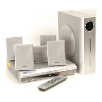
Details on player compatibility, disc formats, and included accessories.
Overview of front panel controls, indicators, and display elements.
Key checks to perform after completing a repair to ensure proper function.
Diagrams showing the physical locations of Printed Circuit Boards within the unit.
List of special jigs and tools required for specific service procedures.
Diagram illustrating the complete wiring interconnections between all major components.
System-level block diagram showing the functional flow of signals and data.
Detailed block diagram of the DVD loader and decoder subsystems.
Procedure for diagnosing laser diode degradation on the optical pickup assembly.
Troubleshooting guide for common issues encountered during DVD playback.
Technical explanation of the digital amplifier circuit's design and operation.
Details on the digital amplifier's protection circuits and their operational parameters.
Troubleshooting steps for issues related to the adapter port, including Bluetooth.
Detailed timeline of operations during the unit's power-on process.
Instructions for entering and operating the unit's diagnostic test mode.
Explanation of the codes and data displayed during the test mode operation.
Details on the functionality of shortcut keys for accessing service modes.
Information on how to display and interpret model-specific data.
Configuration, conditions, and display indications for the service test mode.
Steps to remove the unit's bonnet and tray panel.
Procedure for disassembling and removing the front panel assembly.
Instructions for safely removing the DVD MECHA assembly.
Detailed steps for disassembling individual parts of the DVD MECHA assembly.
Procedure for setting player-specific ID numbers and data for compatibility.
Exploded view and parts list for the unit's packing and accessories.
List of parts included in the packing section, varying by model.
Exploded view illustrating the exterior components of the unit.
List of external parts and their corresponding part numbers.
Detailed list of all parts comprising the DVD MECHA assembly.
Schematic diagram for the 09 DVDM ASSY, first of two pages.
Schematic diagram for the 09 DVDM ASSY, second of two pages.
Schematic diagram for the RHTS SYSMAIN ASSY, first of three pages.
Schematic diagram for the RHTS SYSMAIN ASSY, second of three pages.
Schematic diagram illustrating the RHTS USB ASSY.
Schematic diagram for the RHTS D-AMP ASSY, first of two pages.
Schematic diagram for the RHTS D-AMP ASSY, second of two pages.
Schematic diagram for the EUROSCART ASSY.
Schematic diagram of the unit's power supply circuitry.
Visual representation of key signal waveforms measured at specific points.
PCB connection layout for the 09 DVDM and RHTS USB ASSYS.
PCB connection layout for the RHTS SYSMAIN ASSY.
PCB connection layout for the RHTS D-AMP ASSY.
PCB connection layout for the RHTS DISPLAY ASSY.
PCB connection layout for the EUROSCART ASSY.
List of major assemblies and their part numbers for different models.
Detailed list of individual PCB parts for XV-DV282AP/LXJ models.
Specific PCB parts list for RHTS SYSMAIN ASSY (XWZ4454 model).
Specific PCB parts list for RHTS SYSMAIN ASSY (XWZ4434 model).
Comprehensive list of capacitors with part numbers and their corresponding values.
| Channels | 5.1 |
|---|---|
| DVD Player | Yes |
| Audio Inputs | Analog, Digital Optical, Digital Coaxial |
| Tuner | AM/FM |
| Surround Sound | Dolby Digital, DTS |
| Supported Disc Formats | DVD, CD, MP3, JPEG |
| Video Outputs | Composite, Component |