ORDER NO.
PIONEER CORPORATION 4-1, Meguro 1-chome, Meguro-ku, Tokyo 153-8654, Japan
PIONEER ELECTRONICS (USA) INC. P.O. Box 1760, Long Beach, CA 90801-1760, U.S.A.
PIONEER EUROPE NV Haven 1087, Keetberglaan 1, 9120 Melsele, Belgium
PIONEER ELECTRONICS ASIACENTRE PTE. LTD. 253 Alexandra Road, #04-01, Singapore 159936
PIONEER CORPORATION
2008 Printed in Japan
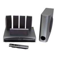
XV-DV575
RRV3748
DVD/CD RECEIVER
XV-DV575
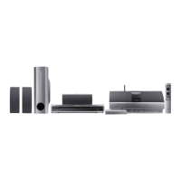
XV-DV580
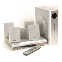
XV-DV385K
XV-DV395K
THIS MANUAL IS APPLICABLE TO THE FOLLOWING MODEL(S) AND TYPE(S).
Model Type Power Requirement
Regional restriction
codes
(Region No.)
Remarks
XV-DV575 WYXJ5 AC 220 V to 240 V 2
XV-DV580 WYXJ5 AC 220 V to 240 V 2
XV-DV580 WVXJ5 AC 220 V to 240 V 2
XV-DV385K WSXJ5 AC 220 V to 240 V 5
XV-DV395K WSXJ5 AC 220 V to 240 V 5
For details, refer to "Important Check Points for good servicing".
T-IZK APR.