Do you have a question about the Pioneer XV-DV434 and is the answer not in the manual?
Details laser power output, wavelength for DVD (650nm) and CD (780nm).
Identifies warning labels and references label VRW1872 for product identification.
Details safety precautions related to laser interlock mechanisms and potential beam exposure.
Emphasizes adherence to product regulations, safety instructions, and maintaining a safe servicing environment.
Outlines procedures for maintaining original product performance through optimum adjustments.
Provides guidelines for using specified lubricants, glues, and replacement parts correctly.
Details procedures for cleaning critical parts like optical pickups and lenses to restore performance.
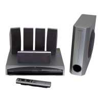
Lists all included accessories with the DVD/CD receiver unit.
Details compatible disc types, formats, logos, and standards like VCD.
Shows an exploded view of the packing configuration and lists associated parts.
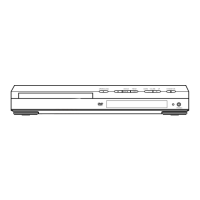
Details the exterior components and their assembly, including an exploded view.
Describes the front panel components and their assembly process.
Details the loader mechanism components and their assembly.
Lists all parts for the traverse mechanism assembly.
Presents a functional block diagram of the DVD/CD receiver system.
Shows the overall wiring connections between major assemblies.
Provides the first part of the DVDM assembly schematic diagram.
Presents the schematic diagram for the DSP assembly.
Shows the schematic diagram for the 6-channel amplifier assembly.
Presents the schematic diagram for the power supply assembly.
Illustrates the PCB connections for the LOAB assembly.
Shows the PCB connection diagram for the DVDM assembly.
Presents the PCB connection diagram for the CONTROL assembly.
Shows the PCB connection diagram for the power supply assembly.
Lists part numbers for various PCB assemblies.
Shows part variations for PCB assemblies across different models.
Lists semiconductor parts for the CONTROL assembly.
Identifies adjustment items and their locations for mechanism and electrical parts.
Lists necessary jigs and measuring instruments for performing adjustments.
Outlines specific adjustment points required when exchanging parts.
Explains how to enter and operate the test mode for diagnostics and functional checks.
Provides detailed steps for mechanism adjustments, such as tangential and radial height.
Covers diagnostic procedures including test modes, error indications, and troubleshooting.
Lists all parts with their respective part numbers, pin functions, and details.
Explains sequences and circuits like power-on steps and protection circuits.
| Type | DVD Receiver |
|---|---|
| Channels | 5.1 |
| DVD Player | Yes |
| Tuner | AM/FM |
| Power Output | 100 W per channel |
| Frequency Response | 20 Hz - 20 kHz |
| Audio Formats | Dolby Digital, DTS |
| Inputs | 1 x Optical, 1 x Coaxial |
| Outputs | Composite |