Do you have a question about the Pioneer XV-DV313 and is the answer not in the manual?
Details specifications for DVD and CD laser diodes, including maximum output power and wavelength.
Provides information regarding label checks, including warnings and cautions for laser safety.
Offers further cautions and details regarding the laser interlock mechanism and exposure prevention.
Emphasizes adherence to regulations and safety instructions during servicing.
Highlights the importance of adjustments for maintaining original product performance and specifications.
Specifies the need for proper cleaning of optical pickups, heads, and lenses to restore performance.
Details procedures for setting shipping mode or installing screws to protect the product during transit.
Guides on the appropriate application of lubricants, glues, and the use of prescribed replacement parts.
Details continuous power output (RMS) for front, center, surround, and subwoofer channels.
Provides specifications for digital audio characteristics, frequency response, and wow/flutter.
Lists the frequency range and antenna specifications for the FM tuner.
Details the frequency range and antenna specifications for the AM tuner.
Covers power requirements, power consumption, dimensions, and weight of the unit.
Lists included accessories such as remote control, batteries, and cables.
Details specifications for front and center speaker systems, including enclosure, impedance, and frequency range.
Lists accessories specific to the speaker system, such as speaker cables and non-slip pads.
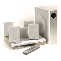
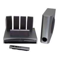
Illustrates the components included in the product packaging and their arrangement.
Provides an exploded view and parts list for the exterior components of the unit.
Details the exploded view and parts list for the front section of the unit.
Shows the exploded view and parts list for the loading mechanism assembly.
Provides specific instructions and diagrams for applying lubricant to the loading mecha assembly parts.
Illustrates the exploded view and parts list for the traverse mechanism assembly.
Provides a high-level overview of the system's functional blocks and their interconnections.
Presents the block diagram and overall wiring for the LOAB assembly.
Details the first part of the DVDM assembly schematic diagram.
Details the second part of the DVDM assembly schematic diagram.
Details the third part of the DVDM assembly schematic diagram.
Details the first part of the DSP assembly schematic diagram.
Details the second part of the DSP assembly schematic diagram.
Presents the schematic diagram for the 6-channel amplifier assembly.
Provides the schematic diagram for the FM/AM tuner module.
Details the schematic diagrams for the control, TRADE3, and TRADE2 assemblies.
Details the second part of the control assembly schematic diagram.
Details the third part of the control assembly schematic diagram.
Details the fourth part of the control assembly and HP assemblies schematic diagrams.
Details the first part of the power supply assembly schematic diagram.
Details the second part of the power supply and TRADE1 assemblies schematic diagrams.
Provides the schematic diagram for the EURO SCART assembly.
Details the schematic diagrams for the display and LED assemblies.
Presents waveform diagrams for various points within the DVDM ASSY for troubleshooting.
Shows the PCB layout and connection points for the LOAB assembly.
Illustrates the PCB layout and component placement for the DVDM assembly.
Shows the PCB layout and component placement for the DSP assembly.
Illustrates the PCB layout and component placement for the 6-channel amplifier assembly.
Shows the PCB layout and component placement for the FM/AM tuner module.
Illustrates the PCB layout and component placement for the control assembly.
Shows PCB layouts for TRADE2, TRADE3, and HP assemblies.
Illustrates the PCB layout and component placement for the power supply assembly.
Shows PCB layouts for TRADE1, EURO SCART, DISPLAY, and LED assemblies.
Lists major assemblies with part numbers, including main boards and modules.
Details specific parts and differences for the CONTROL Assy (XV-DV515 vs XV-DV313).
Describes the adjustment procedure for the FM tuner section, focusing on T-METER adjustment.
Lists mechanism and electrical adjustment items and their locations on the unit.
Specifies the necessary tools and instruments required for performing adjustments.
Details points for adjustment when exchanging mechanism parts or PCB assemblies.
Explains how to enter and operate the unit in test mode for adjustment purposes.
Provides step-by-step procedures for mechanism adjustments like height, jitter, and focus sweep.
Covers diagnostic procedures, including test modes, error history, and troubleshooting.
Explains the functions and operations within the service test mode for unit adjustment and diagnosis.
Details the format and meaning of information displayed on the FL screen during test mode.
Lists command functions and conditions accessible via shortcut keys in the remote control unit.
Explains how model information, region settings, and firmware versions are displayed.
Details service mode functions, including EDC/ID error display and self-diagnosis.
Provides a list of mechanical error codes, servo states, and their descriptions for troubleshooting.
Guides on setting and confirming the player's ID number and data, crucial for DVD-RW CPRM playback.
Offers troubleshooting steps for common issues related to the microcomputer section.
Provides a flowchart for troubleshooting problems with the DSP assembly, especially audio output.
Describes the sequence of operations during power-on, including initialization and mode settings.
Explains the protection circuits (PRTCT WNG, PRTCT ERR, DVD PRTECT) and their causes.
Provides step-by-step instructions for disassembling the unit's bonnet, tray, and loading mechanism.
Outlines specific conditions and requirements for operating in the Service Test mode.
Provides instructions on connecting the unit and entering the Service Test mode.
Explains how to exit Service Test mode and the implications for protection data.
Describes the FL display indications when Service Test mode starts under different conditions.
Details how operations differ in Service Test mode, particularly FL display indications.
Step-by-step instruction for removing the front panel section.
Instruction for removing the CONTROL Assy, noting screw differences for models.
Details the steps for removing the Loading Mecha. Assy from the Traverse Mecha. Assy.
Provides instructions for removing the Traverse Mecha. Assy-S.
Details the procedure for removing the Pickup Assy-S.
Lists integrated circuits used in the DVDM ASSY, including part numbers and basic information.
Details the block diagram and pin functions of the STM6316ATXXA FRONT END IC.
Illustrates the internal architecture and signal flow of the DVDM ASSY FRONT END IC.
Details the pin assignments and functions for the STM6316ATXXA IC.
Details the block diagram and pin functions of the STM5589CVA BACK END IC.
Lists pin names, directions, and functions for the STM5589CVA IC.
Details the M63018FP as the FTS Driver IC, including pin arrangement and block diagram.
Illustrates the physical layout and pin numbering of the M63018FP IC on the DVDM ASSY.
Shows the functional blocks and signal paths within the M63018FP FTS Driver IC.
Details the PDC104A IC as the system control microcomputer, listing its pin functions.
Lists pin names, directions, and functions for the PDC104A system control microcomputer.
Details the BU1924F IC used for RDS/RBDS demodulation, including pin arrangement and function.
Illustrates the physical layout and pin numbering of the BU1924F IC on the CONTROL ASSY.
Lists pin names, directions, and functions for the BU1924F RDS/RBDS Demodulation IC.
Provides information on the player's compatibility with various disc formats and logos.
Details the player's compatibility with CD-R/RW discs, including supported audio/video formats.
Explains compatibility with DVD-R/RW discs, including finalized and VR format, and recording limitations.
Discusses compatibility issues with discs created on personal computers and software publisher information.
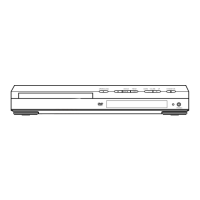
Illustrates and describes the controls and indicators on the front panel of the unit.
Details the various indicators and symbols displayed on the unit's front panel screen.
Explains the speaker indicator displays showing which speakers are used for the current source.
Provides an overview of the remote control, its buttons, and functions.
Describes buttons for starting, pausing, resuming, stopping, and scanning disc playback.
Explains cursor buttons for navigation and ENTER for selection, plus radio tuning buttons.
Details buttons for selecting surround sound modes like AUTO, SURROUND, ADVANCED, and BASS MODE.
Instructions for accessing system setup to configure various system and surround sound settings.
| Type | DVD Receiver |
|---|---|
| Channels | 5.1 |
| Total Power Output | 500 W |
| Audio Formats Supported | Dolby Digital, DTS |
| Tuner | AM/FM |
| JPEG Playback | Yes |
| Remote Control | Yes |
| Weight | 4.5 kg |
| Disc Formats Supported | DVD, CD |
| Audio D/A Converter | 192 kHz/24-bit |
| Inputs | Composite |
| Outputs | Composite, HDMI |