Do you have a question about the Pioneer XV-DV535 and is the answer not in the manual?
Details on laser diode characteristics and product labels.
Guidelines for product safety, adjustments, lubricants, cleaning, and shipping.
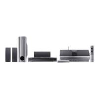
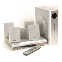
Lists unit specifications, included accessories, and disc compatibility.
Exploded views of packing, exterior, and front panel sections.
Exploded views and parts lists for loader and traverse mechanism assemblies.
Overall functional block diagram of the system.
Detailed wiring diagram showing connections between all system assemblies.
Circuit schematics for the DVDM assembly (parts 1 and 2).
Circuit schematics for various unit assemblies.
Illustrations of signal waveforms for troubleshooting and diagnosis.
PCB connection diagram for the LOAB Assy.
PCB connection diagram for the DVDM Assy.
PCB connection diagrams for DSP, TRADE 2, and TRADE 1 assemblies.
PCB connection diagram for the 6CH AMP Assy.
PCB connection diagram for the CONTROL Assy.
PCB connection diagrams for Display, Video, and LED assemblies.
PCB connection diagram for the POWER Assy.
Lists part numbers for various PCB assemblies and contrast tables.
Details necessary adjustments, tools, and instruments for calibration.
Specific points requiring adjustment after part replacement.
Procedures for entering and operating the unit in test mode.
Steps for adjusting mechanism height and DVD error rate.
Covers diagnosis, test modes, display specifications, shortcut keys, and DSP error messages.
Method to diagnose laser diode degradation on the pickup assembly.
Troubleshooting common DVD playback issues and their solutions.
Procedure for setting player ID numbers for DVD-RW playback.
Guide to identifying and resolving DSP errors.
Steps for disassembling the unit's outer casing and front panel.
Procedures for removing loader, traverse mechanism, and pickup components.
Steps for removing DVDM Assy, flexible cable arrangement, and pickup handling.
List of ICs with pin functions and their roles in the system.
Details the system's startup sequence from power on to normal operation.
Explains conditions triggering PRTCT WNG, PRTCT ERR, and DVD PRTECT errors.
Details circuits protecting against speaker overload, power supply issues, and DC generation.
Explains VDET monitoring for DVD power supply abnormalities.
Describes AC detection circuit for preventing speaker/headphone pops.
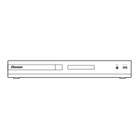
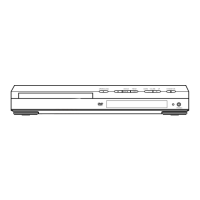
Diagram and labels for the unit's front panel buttons and indicators.
Explains the meaning of various symbols and lights on the unit's display.
Covers standby, source selection, disc playback, and menu navigation controls.
Details settings for MCACC, surround modes, sound adjustments, system setup, and timers.
Guide for connecting and using the unit with a Pioneer plasma display via SR+ cable.
Provides solutions for the SND. DEMO and TRAYLOCK display errors.
Lists necessary jigs, lubricants, glues, and cleaning tools for service.
| Type | DVD receiver |
|---|---|
| Channels | 5.1 |
| DVD Player | Yes |
| Power Output | 100W per channel |
| Dolby Digital | Yes |
| DTS Decoder | Yes |
| Tuner | AM/FM |
| Inputs | digital audio (optical) |
| Outputs | digital audio (optical) |