O
Olivia MeyerAug 3, 2025
What does '96k' mean on my Pioneer XV-EV700 Receiver?
- MmathisjoshuaAug 4, 2025
The '96k' indicator on your Pioneer Receiver appears when the audio source is either 88.2 kHz or 96 kHz PCM.
What does '96k' mean on my Pioneer XV-EV700 Receiver?
The '96k' indicator on your Pioneer Receiver appears when the audio source is either 88.2 kHz or 96 kHz PCM.
Details laser diode specifications, safety precautions, and interlock mechanisms.
Outlines safety measures for repairs, part usage, and environment.
Covers product adjustments, lubricant usage, and cleaning procedures for optimal performance.
Details procedures for shipping mode and securing products during transit to prevent damage.
Details power output, frequency response, S/N ratio, and digital audio characteristics.
Covers cassette deck, FM/AM tuner, power requirements, and physical dimensions.
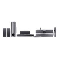
Lists accessories provided with the DVD Tuner Deck Receiver.
Explains the player's compatibility with various disc types and formats, including logos.
Provides an exploded view and parts list for the packing section, including contrast tables.
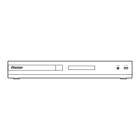
Lists parts for the exterior section, including a contrast table for model differences.
Lists parts included in the amplifier section.
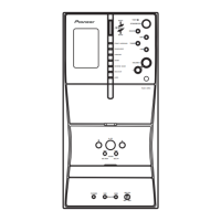
Lists parts for the front panel section, including contrast tables.
Lists parts for the 05 Loader Assembly.
Illustrates the correct application of lubricants on various loader assembly parts.
Lists parts for the Traverse Mechanism Assy-S, including notes on part replacement.
Lists parts for the Deck Mechanism Assembly.
Presents a block diagram illustrating the overall system architecture and signal flow.
Shows the overall wiring connections between various assemblies and their respective pin assignments.
Provides a schematic diagram for the DVDM assembly, part 1 of 2.
Provides a schematic diagram for the DVDM assembly, part 2 of 2.
Presents a schematic diagram for the IFAF assembly, part 1 of 4.
Presents a schematic diagram for the IFAF assembly, part 2 of 4.
Presents a schematic diagram for the IFAF assembly, part 3 of 4.
Presents a schematic diagram for the IFAF assembly, part 4 of 4.
Provides a schematic diagram for the DSP assembly.
Shows the schematic diagram for the Key Assy (XWZ4013).
Shows the schematic diagram for the LED Assy (XWZ4023).
Shows the schematic diagram for the Display Assy (XAV3028).
Provides a schematic diagram for the HP/MIC assembly.
Shows the schematic diagram for the AMP assembly (Side A).
Shows the schematic diagram for the AMP assembly (Side B).
Provides a schematic for the Power Supply Assembly, part 1 of 4.
Provides a schematic for the Power Supply Assembly, part 2 of 4.
Provides a schematic for the Power Supply Assembly, part 3 of 4.
Provides a schematic for the Power Supply Assembly, part 4 of 4.
Illustrates various waveforms measured on the DVDM Assy, related to different test conditions.
Shows the PCB connection diagram for the LOAB assembly, detailing component placement and connections.
Displays the PCB connection diagram for the DVDM assembly, indicating component layout and connector positions.
Provides the PCB connection diagram for the IFAF assembly, showing component layout and connector locations.
Illustrates PCB connection diagrams for Key, LED, and Display assemblies.
Shows the PCB connection diagram for the AMP assembly, detailing component layout.
Provides the PCB connection diagram for the Power Assy, indicating component placement and board layout.
Shows PCB connection diagrams for HP/MIC and Trade assemblies.
Displays PCB connection diagrams for the DSP assembly, detailing component layout.
Lists major assemblies and provides contrast tables for model-specific part differences.
Lists parts for the LOAB and DVDM assemblies, including ICs, transistors, diodes, and resistors.
Lists miscellaneous components, ICs, transistors, diodes, and resistors for the IFAF assembly.
Lists miscellaneous components, ICs, transistors, diodes, capacitors, and resistors for the HP/MIC assembly.
Lists ICs, transistors, and capacitors for the AMP assembly.
Lists components for the DSP assembly, including ICs, resistors, and capacitors.
Lists ICs, transistors, diodes, capacitors, and resistors for the Power Assy.
Details adjustment conditions, lists required tools, and outlines playback/recording adjustments.
Provides detailed procedures for playback and recording adjustments in the deck section.
Specifies adjustment items, locations, required jigs, and test modes for the DVD section.
Provides step-by-step instructions for Tangential and Radial Height Coarse Adjustment.
Outlines the process for adjusting the DVD error rate, including test disc usage and screw adjustments.
Explains how to enter, exit, and the functional specifications of the Test Mode.
Describes the meaning of various indications and codes displayed during Test Mode.
Details the functional specifications of shortcut keys used for service mode operations and model information.
Explains how to display and interpret model information, including destination and version details.
Covers Service Mode display, error rate calculation, and EDC/ID error history.
Outlines conditions, entry, quitting, and indications for the Service Test mode.
Details common DSP errors, their symptoms, and troubleshooting steps.
Explains how to display and interpret DSP error messages, including error codes and their meanings.
Provides a method for diagnosing laser diode degradation by measuring voltages on specific resistors.
Lists common DVD issues, diagnosis steps, and possible defective points.
Lists common symptoms associated with the failure of specific ICs like EEP ROM, Flash ROM, DVD IC, and SDRAM.
Explains the process for setting ID numbers and data, crucial for DVD-RW playback.
Details how to enter and interpret the ID Number Confirmation Mode, including indications for set and unset numbers.
Describes the procedure for entering ID Data Input Mode, writing data to ROM, and handling disc errors.
Provides steps for removing the top bonnet and tray panel, including how to open the tray when power is off.
Guides on diagnosing front panel, amplifier, and DSP boards, and removing the IFAF Assy.
Details the steps for disassembling the Power Amplifier Module, including disconnecting cables and removing screws.
Outlines procedures for diagnosing and removing the DVD Main Board and its associated modules.
Covers removing the 05 LOADER Assy and 05SD Pickup Assy, including tray reinsertion notes.
Provides instructions for dislodking flexible cables and removing the Traverse Mechanism Assy-S.
Details the steps for disconnecting flexible cables, removing adjustment screws, and removing the 05SD Pickup Assy.
Illustrates the proper arrangement of flexible cables for spindle motors and pickup assemblies.
Lists major assemblies and provides contrast tables for model-specific part differences.
Lists parts for the LOAB and DVDM assemblies, including ICs, transistors, diodes, and resistors.
Lists miscellaneous components, ICs, transistors, diodes, and resistors for the IFAF assembly.
Lists miscellaneous components, ICs, transistors, diodes, capacitors, and resistors for the HP/MIC assembly.
Lists ICs, transistors, and capacitors for the AMP assembly.
Lists components for the DSP assembly, including ICs, resistors, and capacitors.
Lists ICs, transistors, diodes, capacitors, and resistors for the Power Assy.