R1224 Regulator
Installation Instruction
24-30-01 12-1001
Page: 6-6 Rev. M: 01 Dec. 2021
© 2021 - Hartzell Engine Technologies - All rights reserved
6.4 Regulator Installation Guide-A
A. General
These regulators were connected via 3 color-coded wires. Cut the wires near the regulator and crimp
appropriate ring lugs onto the wires.
(1) Remove the old regulator.
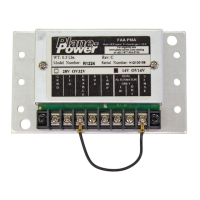
(2) Ensure that the R1224 jumpers are set properly for the aircraft voltage (Fig. 6-1). Verify aircraft electical
system voltage.
(3) Install R1224 Regulator.
(4) Connect the Black wire to R1224 #1 (GND).
(5) Connect the Yellow (Field) wire to R1224 #2 (Field).
(6) Connect the Red (Power) wire to R1224 #3 (Enable).
(7) If applicable for LAMP function, connect a locally manufactured jumper between R1224 #3 (Enable) & #4
(Aux).
(8) For R1224 Rev C and later (Fig. 6-1): Remove jumper between #8 (Sense) and #3 (Enable). Connect the
A (Sense) wire to R1224 #8 (Sense).
If the aircraft was equipped with an overvoltage relay, it may be removed, as the R1224 has internal
overvoltage protection. Splice together the power input and output wires that went to the overvoltage
regulator.
Adjust voltage as necessary with engine running and alternator enabled.
6.5 Regulator Installation Guide-B
A. General
These regulators were connected via 3 color-coded wires. Cut the wires near the regulator and crimp
appropriate ring lugs onto the wires.
(1) Remove the old regulator.
(2) Ensure that the R1224 jumpers are set properly for the aircraft voltage (Fig. 6-1). Verify aircraft electical
system voltage.
(3) Install R1224 Regulator.
(4) Connect the Black wire to R1224 #1 (GND).
(5) Connect the Blue (Field) wire to R1224 #2 (Field).
(6) Connect the Red (Power) wire to R1224 #3 (Enable).
(7) If applicable for LAMP function, connect a locally manufactured jumper between R1224 #3 (Enable) & #4
(Aux).
(8) For R1224 Rev C and later: Remove jumper between #8 (Sense) and #3 (Enable). Connect the A
(Sense) wire to R1224 #8 (Sense).
If the aircraft was equipped with an overvoltage relay, it may be removed, as the R1224 has internal
overvoltage protection. Splice together the power input and output wires that went to the overvoltage
regulator.
(9) Adjust voltage as necessary with engine running and alternator enabled.
 Loading...