R1224 Regulator
Installation Instruction
12-1001 24-30-01
Rev. M: 01 Dec. 2021 Page: 6-9
© 2021 - Hartzell Engine Technologies - All rights reserved
6.9 Regulator Installation Guide-F
A. General
Use two R1224 regulators set for 14V. Use the 12-1021 adaptor plate for mounting (which can be purchased
from Plane-Power). Both regulators must be replaced.
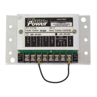
(1) Ensure that the R1224 jumpers are set properly for the aircraft voltage (Fig. 6-1). Verify aircraft electical
system voltage.
(2) Cut the wires close to the regulator case of the Electrodelta or Wico regulators and crimp one appropiate
ring lug with the R1224 on each Red and Blue (or Yellow) wire. Remove remaining wires or insulate the
ends.
(3) Remove the old regulators and the associated Over Voltage Relays (The R1224 has internal over voltage
control so the original units are not needed).Connect the Blue (Field) wire to R1224 #2 (Field).
(4) Install R1224 regulators with 12-1021 adaptor plates in the location from which the original regulators
were removed. Ground is obtained from the mounting so be sure that the regulators are mounted
securely. It is advisable to connect a wire from #1 (Ground) of each R1224 to aircraft ground.
(5) Connect each Blue (or Yellow) wire to #2 (Field) of the corresponding R1224.
(6) Connect each Red wire to #3 (Enable) of the corresponding R1224.
(7) Ensure that there is a jumper between #3 (Enable) and #4 (Aux) of each R1224B. For R1224B Rev C
and later: Ensure there is a jumper between #3 (Enable) and #8 (Sense) of each R1224B.
(8) Connect a wire from the right alternator’s R1224 #6 (In) to the left alternator’s R1224 #7 (Out). This
designates the right R1224 as Slave and the left R1224 as Master for load-sharing operation.
Lamp Modication:
The PA-34-200 is equipped with a press-to-test over voltage Lamp for each alternator/regulator.
6.10 Regulator Installation Guide-G
A. General
These regulators were connected via screw terminals. Label the wires and remove from regulator terminals.
Labeling the wires is important for reconnection. Cut the ring lugs o of the wires crimp the provided (smaller)
ring lugs onto the wires.
(1) Remove old regulator.
(2) Ensure that the R1224 jumpers are set for 14V (Fig. 6-1).
(3) Install R1224 by drilling new mount holes in aircraft or into 12-1021 Adaptor Plate to match the original
regulator mount holes in the aircraft.
(4) Connect the wire marked I to R1224 #3 (ENABLE).
(5) Connect the wire marked F to R1224 #2 (Field).
(6) Jumper R1224 #3 (Enable) to #4 (Aux).
(7) Ensure that there is a jumper between R1224 #8 (Sense) and #3 (Enable).
(8) It is advisable to connect a wire between the aircraft ground (one of the regulator mounting bolts is a
good point) and R1224 #1 (GRND).
(9) Adjust voltage as necessary with engine running and alternator enabled.
 Loading...